Liquid jet head, liquid ejection apparatus, and manufacturing method for the liquid jet head

a technology of liquid jet head and manufacturing method, which is applied in the direction of printing, inking apparatus, etc., can solve the problems of the side walls in the vicinity of the opening portion are not supported anymore, and the electrode formed on the side wall of the elongated groove is also unfortunately ground. , to achieve the effect of high reliability, quick removal of foreign matter, and reduced clogging of the nozzl

Active Publication Date: 2011-05-05
SII PRINTEK
View PDF4 Cites 17 Cited by
  • Summary
  • Abstract
  • Description
  • Claims
  • Application Information

AI Technical Summary

Benefits of technology

[0014]The present invention has been made in view of the above-mentioned circumstances, and it is an object of the present invention to provide a liquid jet head having a structure capable of reducing stagnation and residence of a liquid without requiring a high-degree of machining technology, and to provide a liquid jet apparatus using the liquid jet head, and a manufacturing method for the liquid jet head.
[0026]The liquid jet head according to the present invention includes: the nozzle plate including the nozzle for ejecting the liquid onto the recording medium; the piezoelectric plate including the elongated groove formed at the one surface, and joining the nozzle plate to the another surface; and the cover plate including: the liquid supply hole for supplying the liquid into the elongated groove; and the liquid discharge hole for discharging the liquid through the elongated groove, the cover plate being disposed on the one surface of the piezoelectric plate. In the liquid jet head, the elongated groove of the piezoelectric plate includes the section extending in the longitudinal direction and the depth direction of the elongated groove, the section having the convex shape in the depth direction. The elongated groove is communicated, at the tip of the convex shape, to the nozzle. The elongated groove is communicated, in the bottom portion of the convex shape, to the liquid supply hole and the liquid discharge hole. With this structure, the liquid supplied into the elongated groove flows in from the one surface side having a large opening area of the elongated groove having a convex shape in a bottom portion thereof. Then, the liquid flows out from the same one surface side. Therefore, in the inside region of the elongated groove, the area of the region in which the liquid stagnates is reduced. Thus, it is possible to quickly remove foreign matters such as bubbles and dust from the inside region of the elongated groove. As a result, the clogging of the nozzle is reduced, thereby being capable of providing a highly-reliable liquid jet head.

Problems solved by technology

However, when a part of the bottom surface of the elongated groove is opened, the side walls in vicinity of the opening portion are not supported anymore.
When the PZT sheet 103 is deeply cut from the back side, there cause problems in that the electrode formed on the side wall of the elongated groove is also unfortunately ground, in that the voltage for driving the side wall is fluctuated, because the resistance of the electrode is increased, and the like.

Method used


Image

  • Liquid jet head, liquid ejection apparatus, and manufacturing method for the liquid jet head
  • Liquid jet head, liquid ejection apparatus, and manufacturing method for the liquid jet head
  • Liquid jet head, liquid ejection apparatus, and manufacturing method for the liquid jet head

Examples


first embodiment

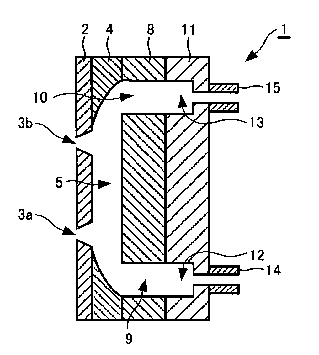
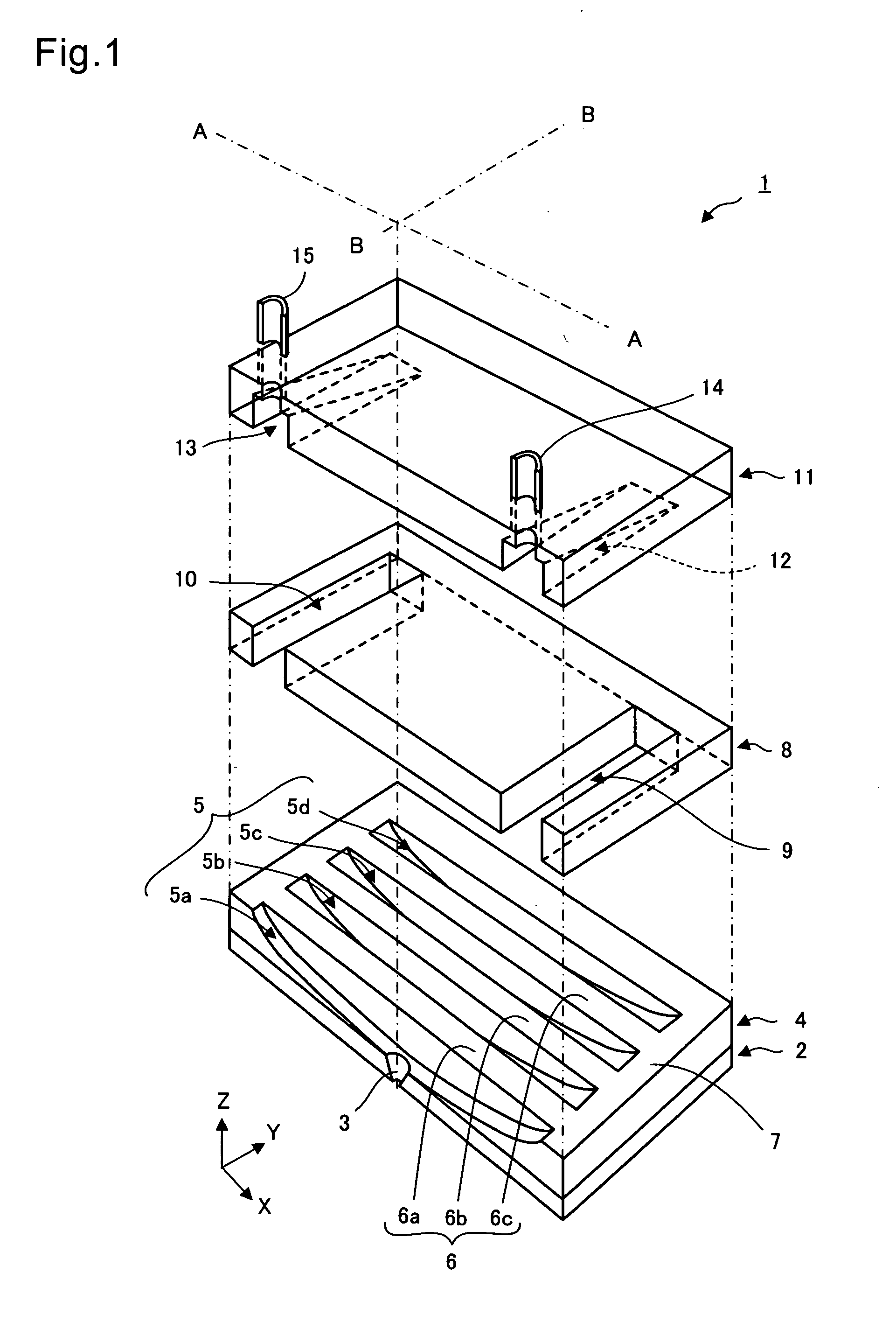
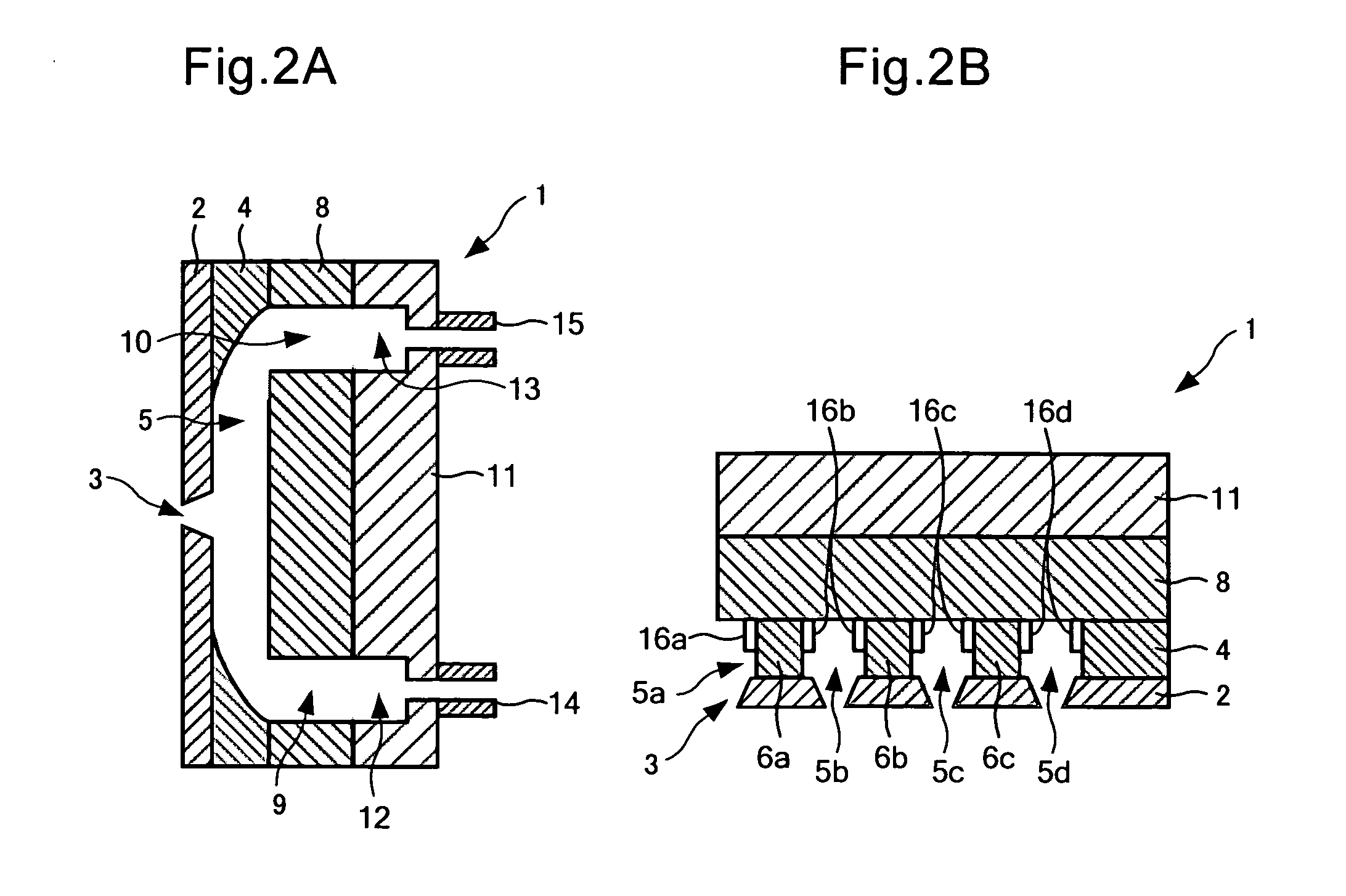
[0045]FIG. 1 is a schematic exploded perspective view of a liquid jet head 1 according to a first embodiment of the present invention. FIG. 2A is a schematic vertical sectional view of the portion AA of FIG. 1, FIG. 2B is a schematic vertical sectional view of the portion BB of FIG. 1, and FIG. 2B is a schematic vertical sectional view of the portion BB of FIG. 1.

[0046]The liquid jet head 1 has a structure in which a nozzle plate 2, a piezoelectric plate 4, a cover plate 8, and a channel member 11 are laminated on each other. As the piezoelectric plate 4, a piezoelectric ceramic including lead zirconate titanate (PZT) can be used, for example. The piezoelectric plate 4 includes, in one surface 7 thereof, a plurality of elongated grooves 5 (5a, . . . 5d). The respective elongated grooves 5a, . . . 5d have a longitudinal direction corresponding to an X-direction, and are arranged in a Y-direction orthogonal to the X-direction. The respective elongated grooves 5a, . . . 5d are defined ...

second embodiment

[0059]FIG. 3 is a schematic vertical sectional view of a liquid jet head 1 according to a second embodiment of the present invention. The second embodiment is similar to the first embodiment except such a difference that the nozzle plate 2 includes two nozzles 3a, 3b corresponding to one groove. In the following, portions of the second embodiment different from those of the first embodiment are mainly described. Further, in the following, the same portions or portions having the same functions as those of the first embodiment are denoted by the same reference symbols.

[0060]As illustrated in FIG. 3, the liquid jet head 1 has a structure in which the nozzle plate 2, the piezoelectric plate 4, the cover plate 8, and the channel member 11 are stacked on each other in this order. The piezoelectric plate 4 includes, in one surface thereof, the elongated groove 5 and the shallow groove 5 arranged to be adjacent to the elongated groove 5 and to be orthogonal to a strip and longitudinal dire...

third embodiment

[0063]FIG. 4 is a schematic vertical sectional view of a liquid jet head 1 according to a third embodiment of the present invention. The third embodiment is similar to the first embodiment except such a difference that the nozzle plate 2 includes the two nozzles 3a, 3b corresponding to one groove 5, and that the cover plate 8 includes the one liquid supply hole 9 and two liquid discharge holes 10a, 10b. In the following, description is made mainly of portions different from those of the first embodiment.

[0064]As illustrated in FIG. 4, the liquid jet head 1 has a structure in which the nozzle plate 2, the piezoelectric plate 4, the cover plate 8, and the channel member 11 are stacked on each other in this order. The piezoelectric plate 4 includes, in one surface thereof, the elongated groove 5 arranged to be adjacent to the elongated groove 5 and to be orthogonal to the longitudinal direction. The elongated groove 5 has a cross-section in the longitudinal direction and the depth dire...


PUM


Abstract

Provided is a liquid jet head (1) capable of reducing stagnation of a liquid in grooves (5) formed in the piezoelectric plate (4) and of quickly discharging foreign matters entered and mixed into the elongated grooves (5). The liquid jet head (1) has a structure in which a nozzle plate (2) including a nozzle (3), a piezoelectric plate (4) for joining the nozzle plate (2), and a cover plate (8) including a liquid supply hole (9) for supplying the liquid and a liquid discharge hole (10) for discharging the liquid are stacked. The elongated groove (5) has a cross-section having a convex shape in the depth direction. The elongated groove is communicated, at a tip of the convex shape, to the nozzle (3). The elongated groove is communicated, in a bottom portion of the convex shape, to the liquid supply hole (9) and the liquid discharge hole (10).

Description

BACKGROUND OF THE INVENTION[0001]1. Field of the Invention[0002]The present invention relates to a liquid jet head for ejecting a liquid from a nozzle to form images, characters, or a thin film material onto a recording medium. The present invention relates also to a liquid jet apparatus using the liquid jet head, and to a manufacturing method for the liquid jet head.[0003]2. Description of the Related Art[0004]In recent years, there has been used an ink-jet type liquid jet head for ejecting ink drops on recording paper or the like to draw and record characters or figures thereon, or for ejecting a liquid material on a surface of an element substrate to form a functional thin film thereon. Further, there has been used a liquid jet apparatus using the above-mentioned ink-jet type liquid jet head. In the ink-jet type liquid jet head, the ink or the liquid material is supplied from a liquid tank through a supply pipe into the liquid jet head, and then the ink is ejected from the nozzle...

Claims


Application Information

Patent Timeline
Patent Type & Authority Applications(United States)
IPC IPC(8): B41J2/045
CPCB41J2/14209B41J2/1609B41J2202/12B41J2/1632B41J2/1623
Inventor KOSEKI, OSAMU
Owner SII PRINTEK
Why Eureka
Try Eureka