
LED Lighting Device

a technology of led lighting and electrodes, which is applied in the direction of semiconductor devices for light sources, lighting and heating apparatus, mechanical apparatus, etc., can solve the problems of easy breakage or burnout of the electrodes of fluorescent lamps, the difficulty of the electrodes at the two ends of fluorescent lamps to generate electron emissions, and the high frequency emi of the sensitive apparatus near the high power, etc., to achieve better illumination efficiency, efficient or effective use, and long operating life

Inactive Publication Date: 2011-05-05
LEDTECH ELECTRONICS CORP
View PDF10 Cites 43 Cited by
  • Summary
  • Abstract
  • Description
  • Claims
  • Application Information

AI Technical Summary

Benefits of technology

[0006]One particular aspect of the present invention is the provision of an LED lighting device, which can provide a lateral light source for efficient or effective use. Compared to fluorescent lamps, the present invention has better illuminating efficiency, longer operating life, and, therefore, the volume of used lamps is less than occurs when fluorescent lamps are used—cost is also improved.
[0009]1. The reflector is disposed in the tubular housing and has the mentioned chevron reflecting portion, which faces the light emitting unit for reflecting the light source to the two lateral directions of the tubular housing. Thus, the light source is used efficiently and effectively. When compared with fluorescent lamps, the present invention is able to increase brightness rather than using more lamps. In this manner, the number or concentration of lamps can be reduced.
[0010]2. In comparison with fluorescent lamps, the light emitting diodes generate higher temperatures when operating. Thus, the illumination efficiency is not reduced in the low temperature environment. Moreover, there are no burned-out or broken electrodes. Thus operating life is increased significantly, and the costs are saved.

Problems solved by technology

In the low temperature environment of the ice tank, it is difficult for the electrodes at two ends of the fluorescent lamp to generate electron emissions, for this reason high power fluorescent lamps are used to overcome the problem.
However, the high power fluorescent lamp radiates high frequency electromagnetic interference (EMI), the high frequency EMI would destroy the sensitive apparatus near the high power fluorescent lamp.
Moreover, the electrodes of fluorescent lamps are easily broken or burn out in the low temperature environment through vibration or wide temperature variation.
The operating life of the fluorescent lamp in these environments is short to the point that maintenance is significant, thereby causing significant levels of replacement of the damaged or broken fluorescent lamps over short intervals.
Aside from this, or in addition, the light direction of the fluorescent lamp is radiative, so that a part of the light illumination is blocked by the inner wall of the ice tank, thereby reducing the inside brightness of the ice tank to a point approaching simple ineffectiveness.
Certainly, overall costs increase.
The light direction of the fluorescent lamps is radiative, rather than lateral, so that there is not enough bright illumination for the art painting which is at one side of the fluorescent lamps.
This results in higher cost.

Method used


Image

  • LED Lighting Device
  • LED Lighting Device
  • LED Lighting Device

Examples


Embodiment Construction

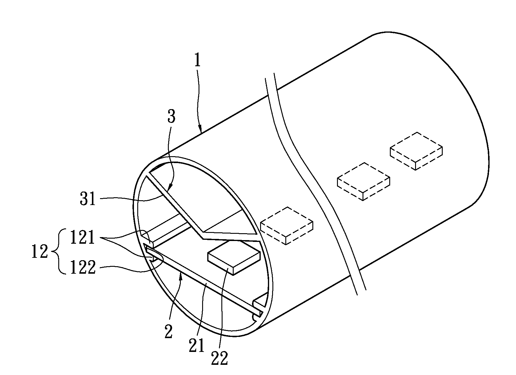
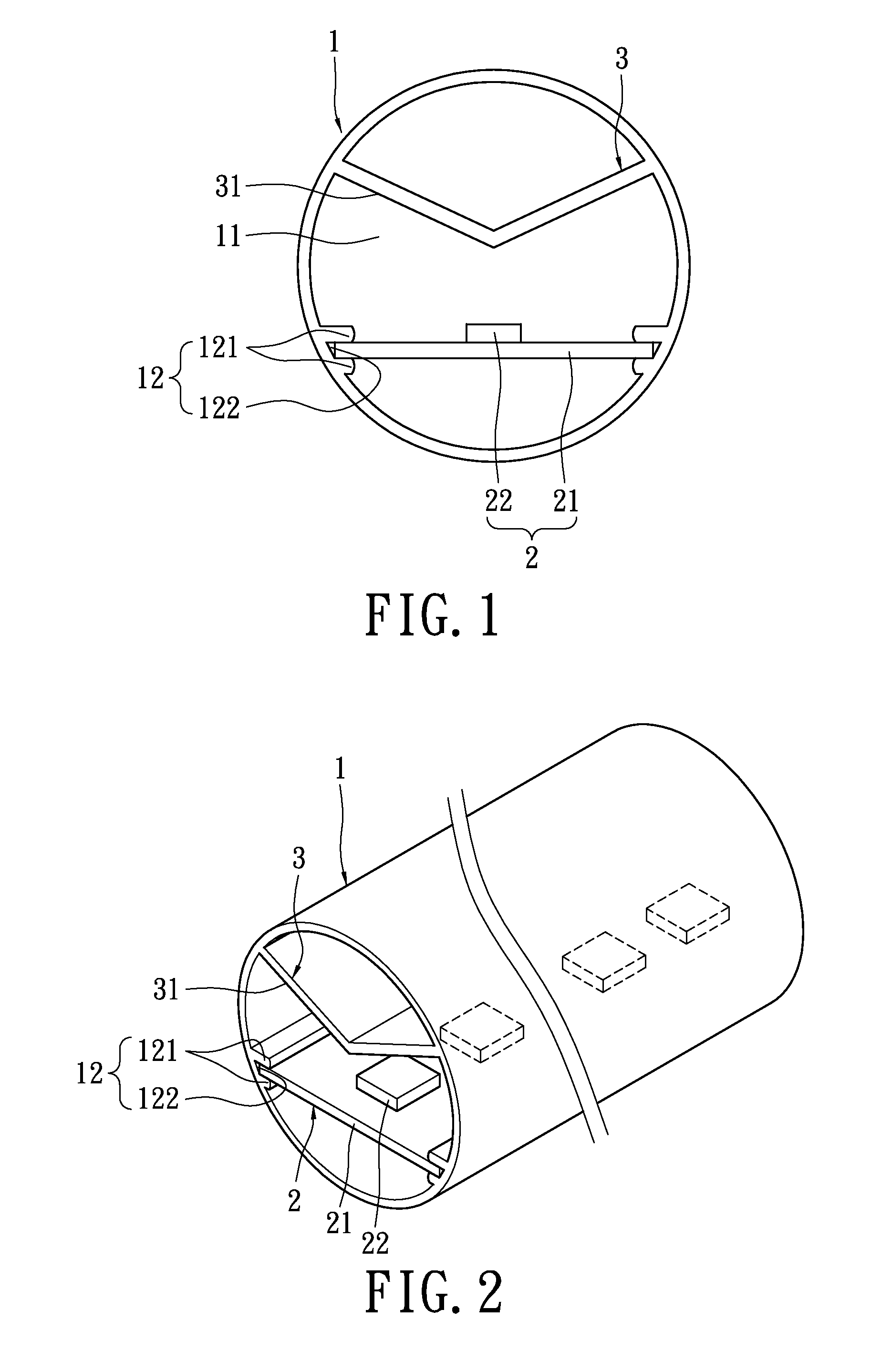
[0024]Reference is made to FIGS. 1 and 2. The LED lighting device can be used in an ice tank or wall painting (please refer to FIG. 11 and FIG. 12), includes a tubular housing 1, a light emitting unit 2, and a reflector 3.

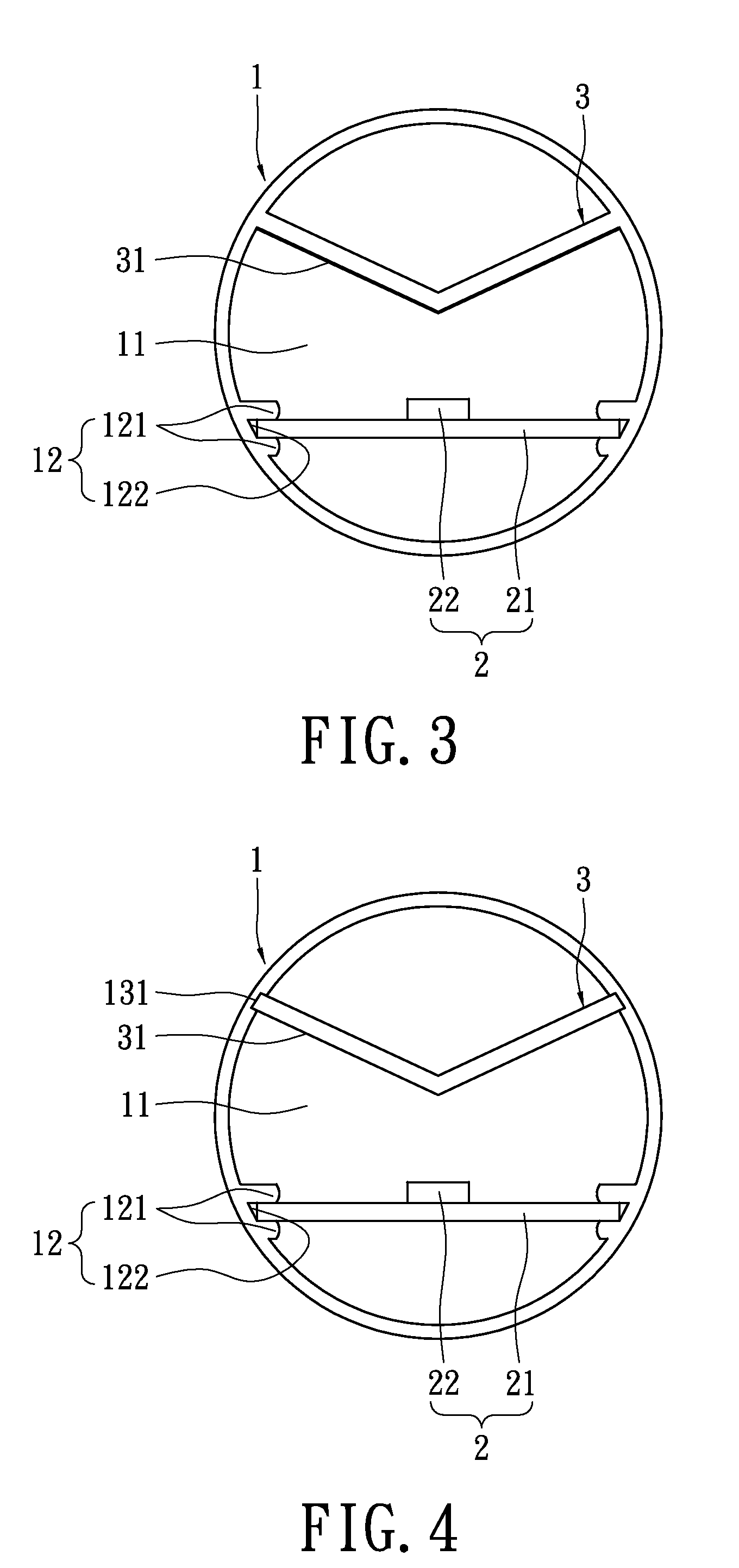
[0025]In this embodiment, the tubular housing 1 is made of plastic, for example, including polycarbonate, acrylic or other appropriate materials. The tubular housing 1 is shaped into a transparent or translucent hollow column, but not limited to it. Compared to the tube of fluorescent lamp, the weight and the cost are reduced. The tubular housing 1 has an accommodating space 11 and an accommodating portion 12 therein. The accommodating portion 12 has four ribs 121, which protrude from and are disposed on the inner wall of the tubular housing 1 and have a face-to-face arrangement. An accommodating groove 122 is formed between two adjacent ribs 121 for disposing the light emitting unit 2 therein.

[0026]The light emitting unit 2 comprises an aluminum substrate 21 and a...


PUM


Abstract

The LED lighting device includes a tubular housing, a light emitting unit, and a reflector. The tubular housing has an accommodating space. The light emitting unit is disposed in the accommodating space and has a plurality of light emitting diodes. The reflector is disposed in the accommodating space and has a wing-shaped reflecting portion. The reflecting portion faces the light emitting unit for reflecting the light source emitted from the light emitting diodes to the lateral directions of the tubular housing. As a result, the light source can be converted to a specific direction. Compare to the fluorescent lamps, the present invention has higher illumination efficiency and a longer operating life. The volume of the lamps and the cost are saved.

Description

BACKGROUND OF THE INVENTION[0001]1. Field of the Invention[0002]The present invention relates to an LED lighting device. In particular, the present invention relates to an LED lighting device that has a lateral light source.[0003]2. Description of Related Art[0004]Most ice tanks still use fluorescent lamps therein for lighting at present. In the low temperature environment of the ice tank, it is difficult for the electrodes at two ends of the fluorescent lamp to generate electron emissions, for this reason high power fluorescent lamps are used to overcome the problem. However, the high power fluorescent lamp radiates high frequency electromagnetic interference (EMI), the high frequency EMI would destroy the sensitive apparatus near the high power fluorescent lamp. Moreover, the electrodes of fluorescent lamps are easily broken or burn out in the low temperature environment through vibration or wide temperature variation. The operating life of the fluorescent lamp in these environmen...

Claims


Application Information

Patent Timeline
IPC IPC(8): F21V1/00F21V7/00F21V29/00
CPCF21V5/002F21V7/0008F21V15/013F21V17/104F21Y2103/003F21W2131/304F21W2131/305F21Y2101/02F21V29/004F21Y2103/10F21Y2115/10F21K9/275F21K9/68F21V29/74
Inventor CHEN, WEI-CHUNWANG, FANG-POWANG, YAO-I
Owner LEDTECH ELECTRONICS CORP
Learn More