
Jig device and apparatus and method of making a dental prosthesis or pattern therefor

a dental prosthesis and pattern technology, applied in the direction of impression caps, process and machine control, instruments, etc., can solve the problems of time-consuming manual hand work and dental prosthesis

Active Publication Date: 2011-05-05
OBRIEN DENTAL LAB
View PDF16 Cites 25 Cited by
  • Summary
  • Abstract
  • Description
  • Claims
  • Application Information

AI Technical Summary

Benefits of technology

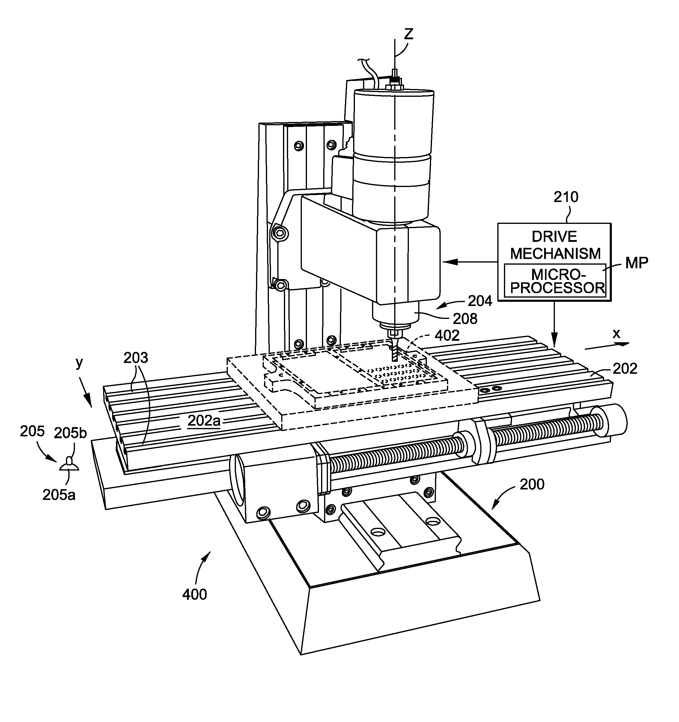
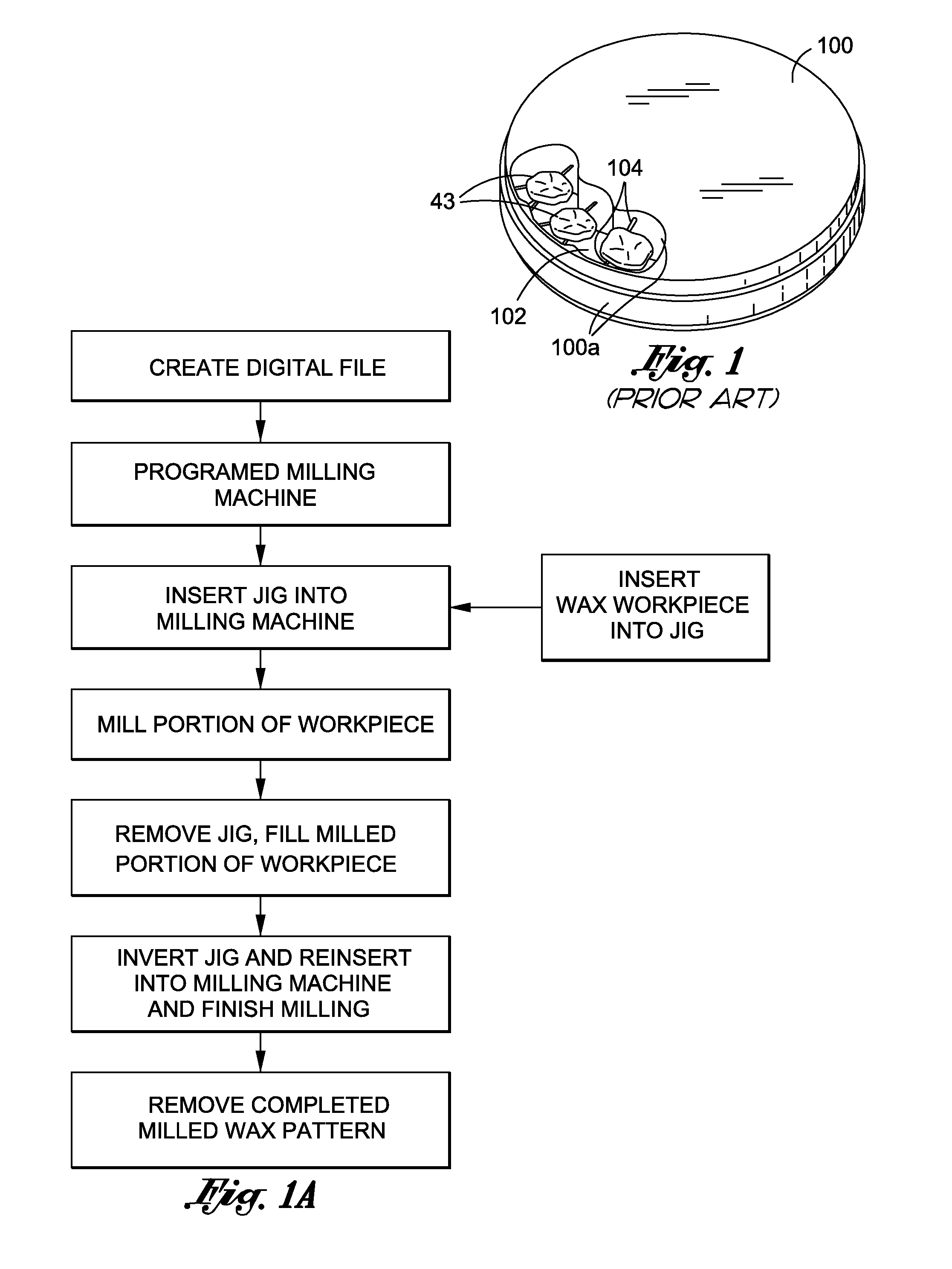
[0014]Four, our apparatus makes a prosthesis from a two-sided work piece, and it includes a milling machine and a holder for the work piece that enables the work piece to be inverted. Our jig device and milling machine have interactive elements that enable the jig device to be repeatedly inserted, removed and inverted, and then reinserted into the milling machine at the same predetermined location with each insertion, or reinsertion after inverting. Consequently, our milling machine may be programmed to operate so the cutting tool precisely cuts from the work piece a prosthesis having a surface essentially free of defects. The work piece is moved from a first position, presenting to the milling machine's cutting tool a first side of the work piece, to a second position presenting to the cutting tool a second side of the work piece. A drive mechanism for the milling machine is initially operated when the work piece is in the first position so the cutting tool partially cuts through the first side of the work piece, to drill away a substantial portion of material from the work piece, while avoiding penetrating through the work piece with the tip of the cutting tool. This forms in one side of the work piece a cavity having a surface part corresponding to at least a portion of the prosthesis being made. The drive mechanism may move the tabletop from the start position laterally along the working reference plane in one or the other of orthogonal directions and rotates and moves the cutting tool from the start position towards and away from the tabletop along a straight line following the tool's longitudinal centerline. The drive mechanism returns the cutting tool and the tabletop to their respective start positions after partially cutting through the one side of the work piece to enable filling the cavity at least partially with the support material. The drive mechanism is operated to completely cut through the opposite side of the work piece after filling the cavity with support material to finish making a prosthesis having a surface essentially free of defects.
[0015]In one embodiment of our apparatus, the milling machine's planar tabletop may be mounted to move laterally in a straight line along the working reference plane in one or the other of orthogonal directions. The cutting tool may be mounted to rotate and to move towards and away from the tabletop along a straight line. The cutting tool's longitudinal centerline may be normal to the working reference plane and intersects a reference point on the working reference plane when the tabletop and cutting tool are in the start positions. A locating structure for positioning the jig device in a predetermined location is on the tabletop. The locating structure enables an operator to manually insert the jig device into the milling machine at a predetermined location so the jig device and milling machine are in an exact spatial relationship allowing the cutting tool to precisely cut from the work piece the prosthesis being made. This locating structure may comprise a detachable platform including a pair of aligned vertical post elements projecting outward from the tabletop. It may be designed to position the jig device with a surface of the jig device adjacent, and substantially parallel to, the planar tabletop.

Problems solved by technology

The problem with conventional milling machines and methods for making a dental prosthesis is the time consuming manual hand work required, after completion of the milling process, to eliminate surface defects.

Method used


Image

  • Jig device and apparatus and method of making a dental prosthesis or pattern therefor
  • Jig device and apparatus and method of making a dental prosthesis or pattern therefor
  • Jig device and apparatus and method of making a dental prosthesis or pattern therefor

Examples


Embodiment Construction

.” The claims that follow define our jig device and apparatus and method of making a prosthesis, distinguishing them from the prior art; however, without limiting the scope of our jig device and apparatus and method of making a prosthesis as expressed by these claims, in general terms, some, but not necessarily all, of their features are:

[0010]One, in our method a milling machine mills from a two-sided work piece a dental prosthesis essentially free of defects. The milling machine has a cutting tool that terminates at a cutting tip that has, at a start position, an exact spatial relationship with respect to a working reference plane of the milling machine. A first side of the work piece is presented to the cutting tool, and starting from the start position, the cutting tool is operated to partially cut through the first side to form in the work piece a cavity having a surface part corresponding to at least a portion of the prosthesis being made. A floor of the cavity may include the...


PUM

PropertyMeasurementUnit
distanceaaaaaaaaaa
distanceaaaaaaaaaa
open areaaaaaaaaaaa

Abstract

A jig device holding a work piece is used with a milling machine that cuts from the work piece a prosthesis having a surface essentially free of defects. The jig device is inserted repeatedly into the machine in the same predetermined location, even upon inverting the jig device. This maintains the spatial relationship between the jig device and milling so, at start up, they are always in the same exact spatial relationship. The milling machine partially cuts through a first side of the work piece to form in the work piece a cavity having a surface part corresponding to at least a portion of the prosthesis being made. The jig device is then removed from the machine, inverted and reinserted into the machine at the same predetermined location. A support material is placed in the cavity prior to reinserting the jig device. Upon reinserting the jig device, the machine precisely cuts through an opposed side of the work piece to form within the work piece a prosthesis having a surface essentially free of defects. The prosthesis is supported within the work piece by the support material. The prosthesis and support material are separated to complete our method.

Description

INCORPORATION BY REFERENCE[0001]Any and all U.S. patents, U.S. patent applications, and other documents, hard copy or electronic, cited or referred to in this application are incorporated herein by reference and made a part of this application.DEFINITIONS[0002]The words “comprising,”“having,”“containing,” and “including,” and other forms thereof, are intended to be equivalent in meaning and be open ended in that an item or items following any one of these words is not meant to be an exhaustive listing of such item or items, or meant to be limited to only the listed item or items.[0003]In the claims, the words “prosthesis” or “prostheses” shall mean a dental prosthesis or a pattern for making a dental prosthesis.[0004]The word “rectangular” includes square.[0005]The words “substantially” and “essentially” have equivalent meanings.BACKGROUND[0006]Computer technology has advanced to the point where a dental prosthesis may be milled from a solid block of material based on three-dimensio...

Claims


Application Information

Patent Timeline
Patent Type & Authority Applications(United States)
IPC IPC(8): A61C8/00G05D3/00A61C5/77
CPCA61C9/0053A61C13/0004A61C13/081Y10T409/308792Y10T409/30616Y10T409/307504Y10T409/303808Y10T409/3056A61C5/70A61C13/0022A61C5/77Y10T409/307Y10T409/30868Y10T408/563A61C13/0003A61C13/0006B23C3/00B23C2226/18B23C2270/08
Inventor LUKSCH, DERRICKLUKSCH, CHRISTPHORUS
Owner OBRIEN DENTAL LAB
Learn More