Mechanical Model of the Cardiovascular System and Method of Demonstrating the Physiology of the Cardiovascular System

a mechanical model and cardiovascular system technology, applied in the field of anatomy modeling, can solve the problems of inability to accurately study peripheral vascular flow, and inability to demonstrate appropriate diastolic volumes

Active Publication Date: 2011-05-05
UNIVERSITY OF SCRANTON
View PDF19 Cites 9 Cited by
  • Summary
  • Abstract
  • Description
  • Claims
  • Application Information

AI Technical Summary

Benefits of technology

[0028]The invention includes a hydraulic model of the cardiovascular system for illustrating a plurality of physiological concepts and relationships including arterial compliance, venous compliance, and peripheral resistance, said model comprising: a.) a cardiac subsystem for moving a fluid in a singular direction in a closed hydraulic system; b.) an arterial subsystem for modeling arterial compliance, the arterial subsystem fluidically coupled with the cardiac subsystem to receive the fluid discharged from the cardiac subsystem; c.) a peripheral resistance subsystem for modeling peripheral resistance, the peripheral resistance subsystem

Problems solved by technology

Clearly the impact of any change in radius will greatly affect resistance and thereby flow.
Poiseuille's law is utilized in studying peripheral vascular flow but can be inaccurate because of the largely non-Newtonian behavior of blood in the smaller vessels.
A great challenge to these mechanical systems is the illustration of the “Law of the Heart.” Bag-like ventricles have been utilized for modeling the passively-filling nature of t

Method used


Image

  • Mechanical Model of the Cardiovascular System and Method of Demonstrating the Physiology of the Cardiovascular System
  • Mechanical Model of the Cardiovascular System and Method of Demonstrating the Physiology of the Cardiovascular System
  • Mechanical Model of the Cardiovascular System and Method of Demonstrating the Physiology of the Cardiovascular System

Examples


Embodiment Construction

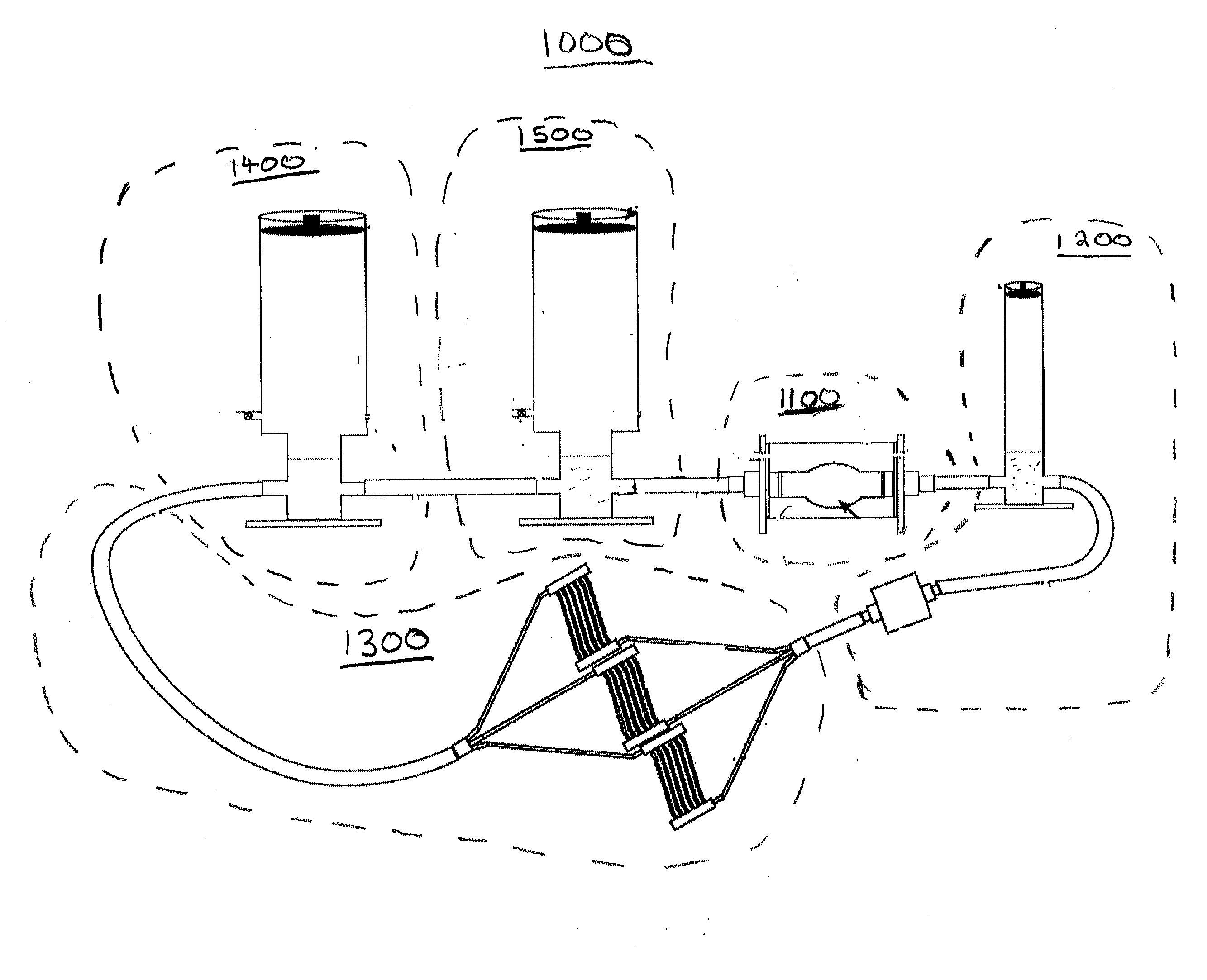
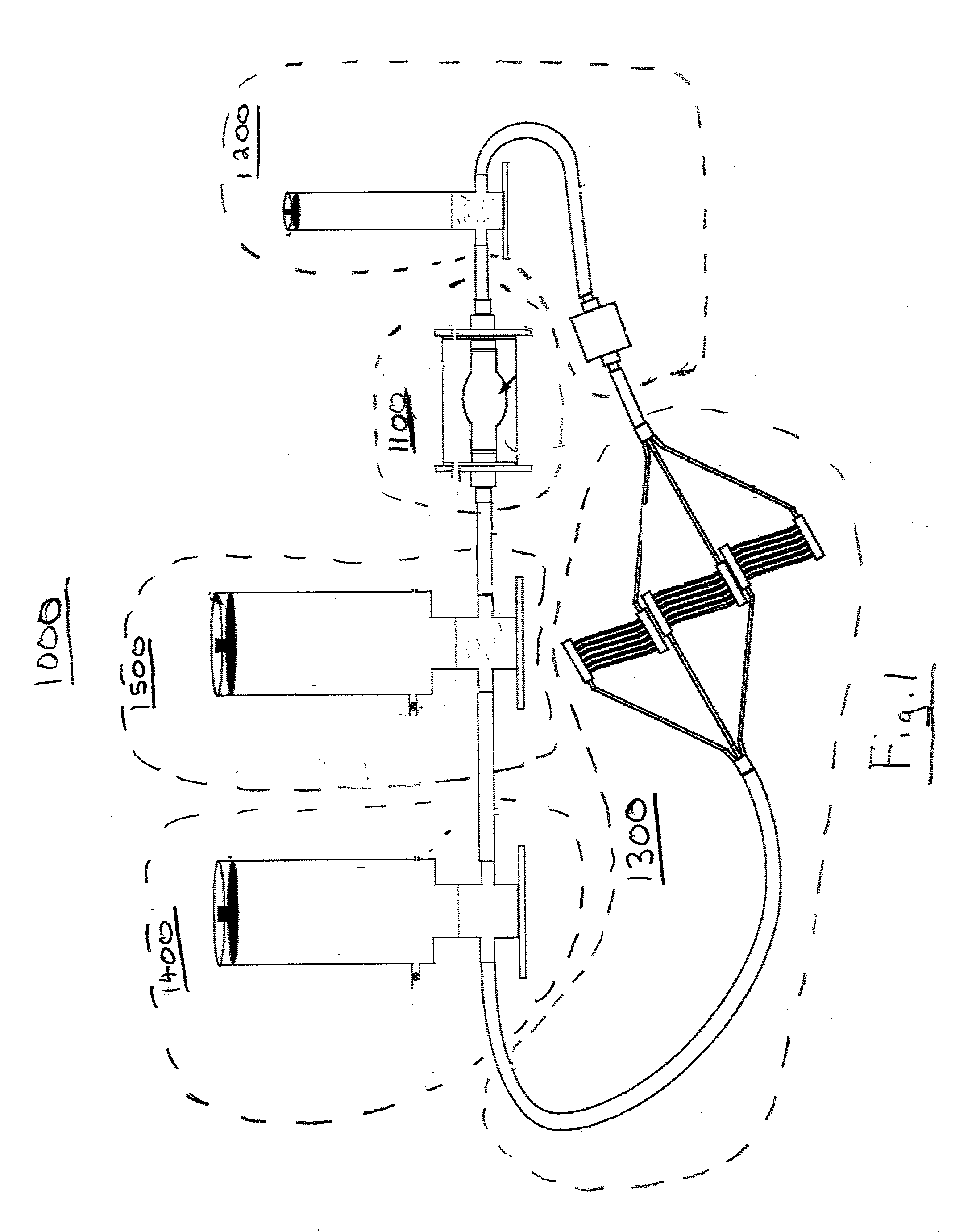
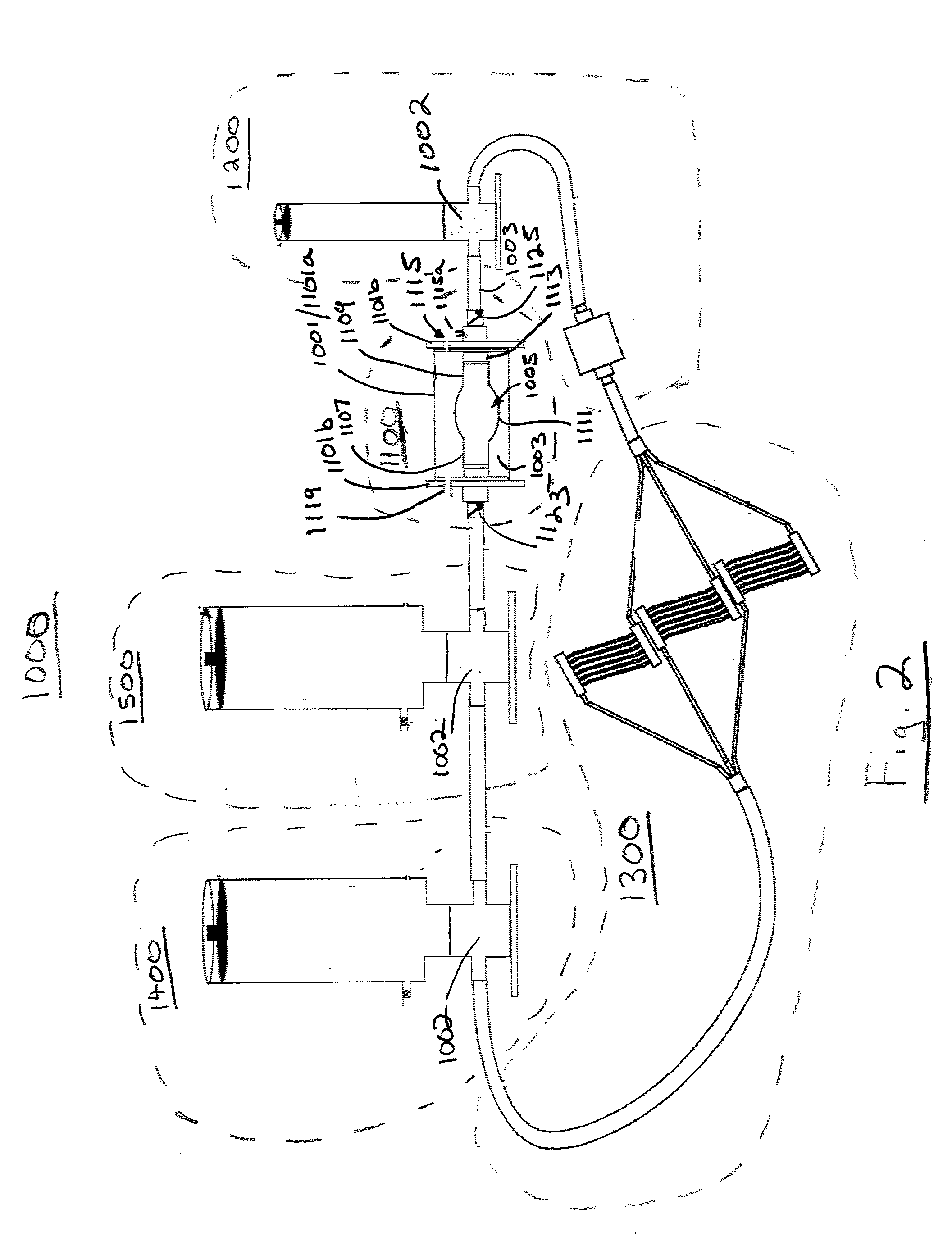
[0088]The invention relates generally to a hydraulic model of the cardiovascular system used to illustrate a plurality of physiological concepts and relationships including arterial compliance, venous compliance, arterial resistance, the various effects of ventricular filling pressure and filling time on cardiac stroke volume, hypertension and exercise.

[0089]The cardiovascular model is a plurality of subsystems that operate together with the assistance of a computer, electromechanical controls, and manually operated parameters. The subsystems include a.) a cardiac subsystem for moving a fluid in a singular direction in a closed hydraulic system; b.) an arterial subsystem for modeling arterial compliance, the arterial subsystem fluidically coupled with the cardiac subsystem to receive the fluid discharged from the cardiac subsystem; c.) a peripheral resistance subsystem for modeling peripheral resistance, the peripheral resistance subsystem fluidically coupled with the arterial subsy...


PUM


Abstract

A hydraulic model of the cardiovascular system for illustrating a plurality of physiological concepts and relationships including arterial compliance, venous compliance, and peripheral resistance, said model comprising: a.) a cardiac subsystem for moving a fluid in a singular direction in a closed hydraulic system; b.) an arterial subsystem for modeling arterial compliance, the arterial subsystem fluidically coupled with the cardiac subsystem to receive the fluid discharged from the cardiac subsystem; c.) a peripheral resistance subsystem for modeling peripheral resistance, the peripheral resistance subsystem fluidically coupled with the arterial subsystem to receive the fluid discharged from arterial subsystem; d.) a peripheral venous (PV) subsystem for modeling peripheral venous compliance and for modeling a peripheral venous pump (PVP), the peripheral venous subsystem fluidically coupled with the peripheral resistance subsystem to receive the fluid discharged from the at least one downstream conduit; and e.) a central venous (CV) subsystem for modeling central venous compliance and for modeling a thoracic pump (TP), the CV subsystem fluidically coupled with the PV subsystem to receive the fluid discharged from the PV subsystem and to pass the fluid to the cardiac subsystem to complete the cardiovascular cycle.

Description

CROSS REFERENCE TO RELATED APPLICATIONS[0001]This application claims priority to U.S. provisional application Ser. No. 61 / 257,932 filed on Nov. 4, 2009, and is incorporated by reference as if set forth entirely herein.BACKGROUND OF INVENTION[0002]a. Field of Invention[0003]The invention relates generally to anatomical modeling. Particularly, the invention relates to a mechanical model of the cardiovascular system for demonstrating physiological principles related to the cardiovascular system including arterial compliance, venous compliance, arterial resistance, the various effects of ventricular filling pressure and filling time on cardiac stroke volume, hypertension and exercise.[0004]b. Background of the Invention and Description of Related Art[0005]The cardiovascular system is basically a pressure driven transport system, moving its constituents macroscopic distances within an organism, coupled to diffusional transport systems that move constituents microscopic distances. The inv...

Claims


Application Information

Patent Timeline
IPC IPC(8): G09B23/30
CPCG09B23/32G09B23/12
Inventor SWEENEY, TERRENCE E.
Owner UNIVERSITY OF SCRANTON
Why Eureka
Try Eureka