Finishing machine

a technology for finishing machines and belts, applied in the direction of grinding machines, grinding machine components, construction, etc., can solve the problems of time-consuming and difficult to move, and achieve the effect of reducing labor intensity and reducing labor intensity

Inactive Publication Date: 2011-05-05
PEAKE ALAN THOMAS
View PDF6 Cites 2 Cited by
  • Summary
  • Abstract
  • Description
  • Claims
  • Application Information

AI Technical Summary

Benefits of technology

Preferably the drive belt runs on taper lock pulleys which allow quick release.

Problems solved by technology

However both these machines have a number of deficiencies; the dust collection apparatus is ineffective, they are difficult to move when not in operation and changing worn belts is time consuming.

Method used


Image

  • Finishing machine
  • Finishing machine
  • Finishing machine

Examples


Embodiment Construction

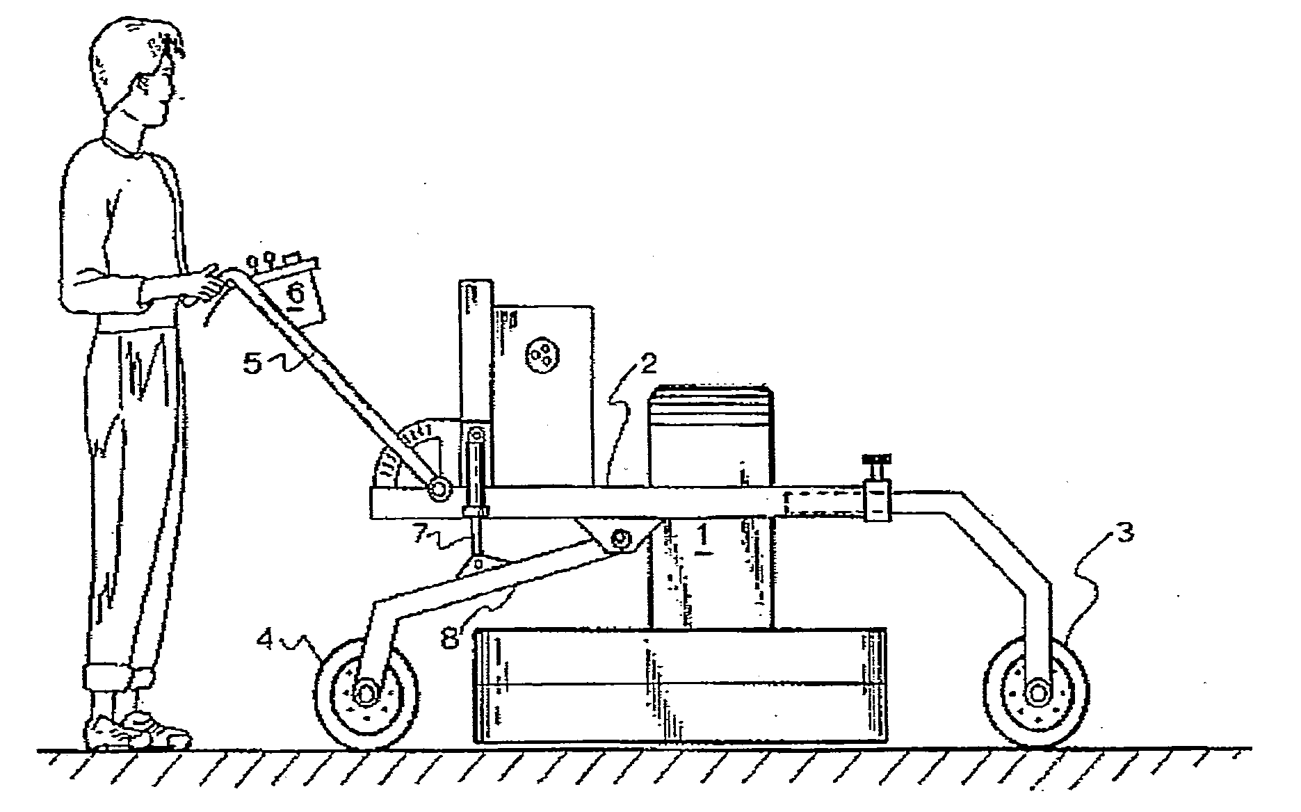
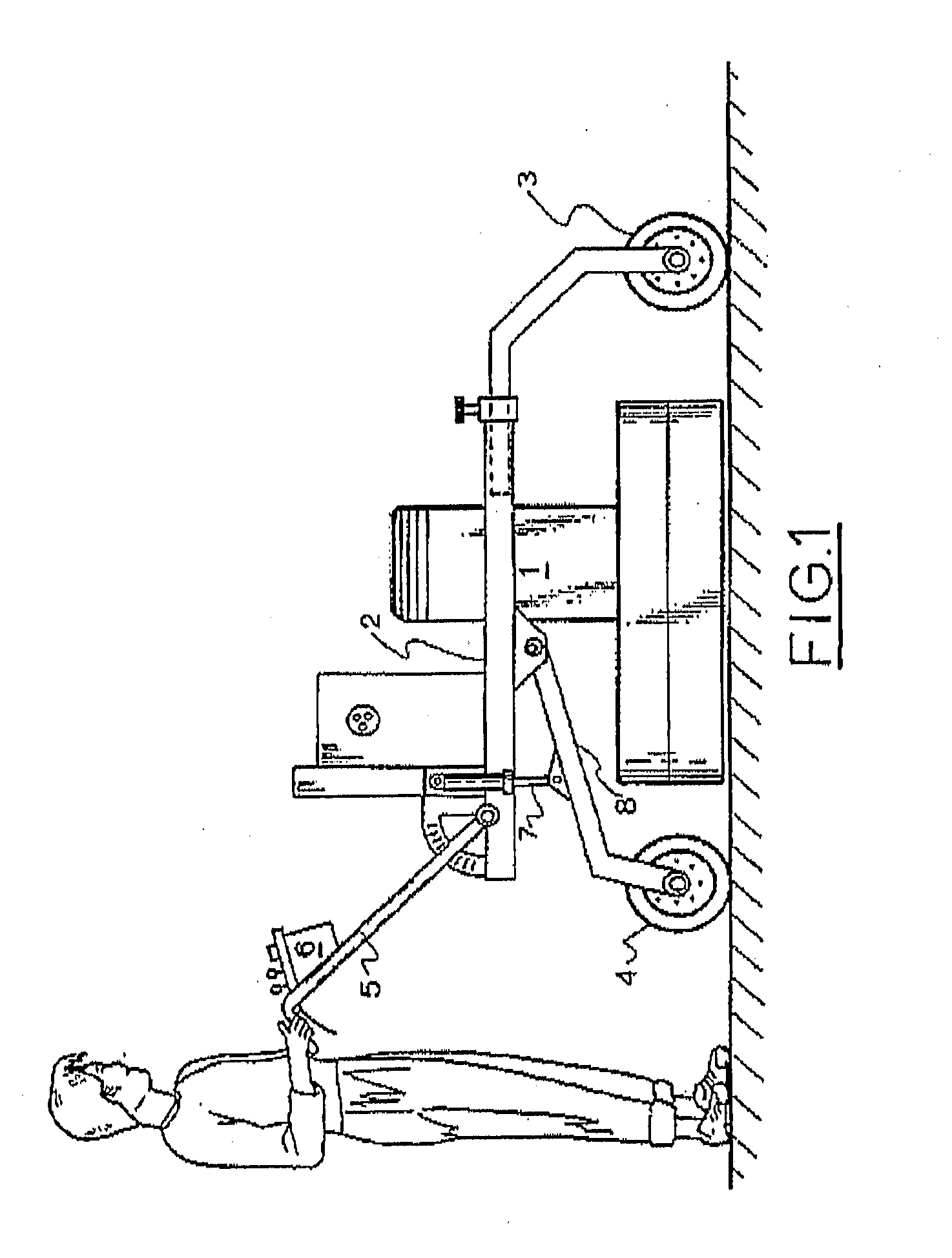
FIG. 1 illustrates an operator using a finishing machine which has motor 1 mounted on frame 2 with removable front wheels 3 and adjustable rear wheels 4. Handles 5 have a control box 6 mounted within reach of the operator. As well as switching the machine on and off box 6 controls height adjustment by operating hydraulic cylinder 7 to rotate rear wheel strut 8 up or down. Accordingly when not in use strut 8 is lowered and the machine can be easily wheeled to another location.

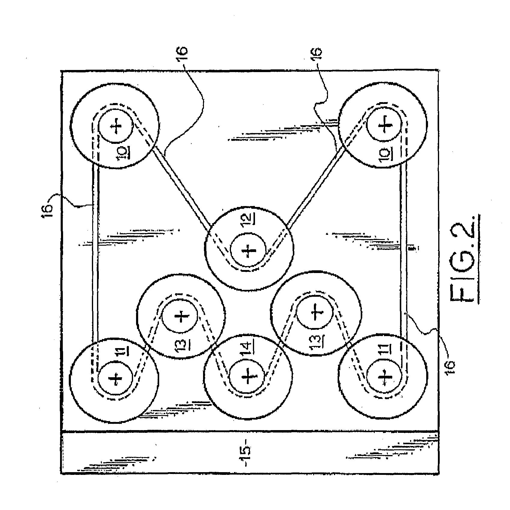
FIG. 2 shows the configuration of grinding head assemblies with a pair 10 at the front corners, a pair 11 at the rear corners, one 12 in the centre and a pair 13 between the centre and the rear corners. The assembly 14 midway between the rear corners does not have a grinding head but is a fan which impels dust into a vacuum manifold 15 at the rear of the assemblies.

Motor 1 drives assembly 12 through a direct drive flexible coupling (not shown) and assembly 12 drives assemblies 10, 11, 13 and 14 via serpentine be...


PUM


Abstract

A finishing machine comprises a motor mounted on a support frame and connected to a drive shaft and two or more finishing heads and an impeller fan driven by the drive shaft via a serpentine belt drive which rotates the finishing heads in opposite directions. The impeller fan impels dust from the grinding heads into a rear vacuum manifold and the support frame has rear wheels the height of which is adjustable by means of an hydraulic cylinder.

Description

FIELD OF THE INVENTIONThis invention relates to machines for finishing surfaces such as grinders for polishing concrete floors.BACKGROUND OF THE INVENTIONU.S. Pat. No. 6,494,772 discloses a floor conditioning machine which provides a random rotating orbital action and includes a main housing, wheel assembly, a handle assembly, a motor, a belt cover, a belt, a dust recovery system and orbital head assemblies. The belt drive utilizes a serpentine configuration which rotates head assemblies in opposite directions so that torque is reduced and the machine is therefore easy to control and steer.AU Patent Application 1006202204 discloses a machine which also utilizes a serpentine belt drive. A primary pulley is driven by a motor and the belt drives pulleys which rotate head assemblies in opposite directions. However both these machines have a number of deficiencies; the dust collection apparatus is ineffective, they are difficult to move when not in operation and changing worn belts is ti...

Claims


Application Information

Patent Timeline
Patent Type & Authority Applications(United States)
IPC IPC(8): B24B7/00
CPCB24B7/186E04F21/24B24B47/10B24B41/047E04F21/248
Inventor PEAKE, ALAN THOMAS
Owner PEAKE ALAN THOMAS
Why Eureka
Try Eureka