Inter vial transfer system

a transfer system and vial technology, applied in the direction of pharmaceutical containers, packaging foodstuffs, packaged goods types, etc., can solve the problems of limited access to the same, high degree of care when using such toxic components, and one of the components of the pharmaceutical composition can be considered dangerous, so as to achieve the effect of minimizing the access to individual components

Inactive Publication Date: 2011-05-05
DUOJECT MEDICAL SYSTEMS INC
View PDF13 Cites 20 Cited by
  • Summary
  • Abstract
  • Description
  • Claims
  • Application Information

AI Technical Summary

Benefits of technology

[0006]It is an object of the present invention to provide a fluid transfer assembly for pharmaceutical delivery systems wherein access to the individual components is minimized.
[0018]In one particular embodiment, the needle may have an offset arrangement such that access through the needle to the vial is prevented. If desired, a tamper evident seal may be provided between the point of joinder of the vial socket and housing.

Problems solved by technology

Some medical treatments require the administration of a pharmaceutical composition wherein one of the components of the pharmaceutical composition can be considered to be dangerous due to toxicity or other factors.
Naturally, great care must be exercised when using such toxic components and access to the same needs to be limited.

Method used


Image

  • Inter vial transfer system
  • Inter vial transfer system
  • Inter vial transfer system

Examples


Embodiment Construction

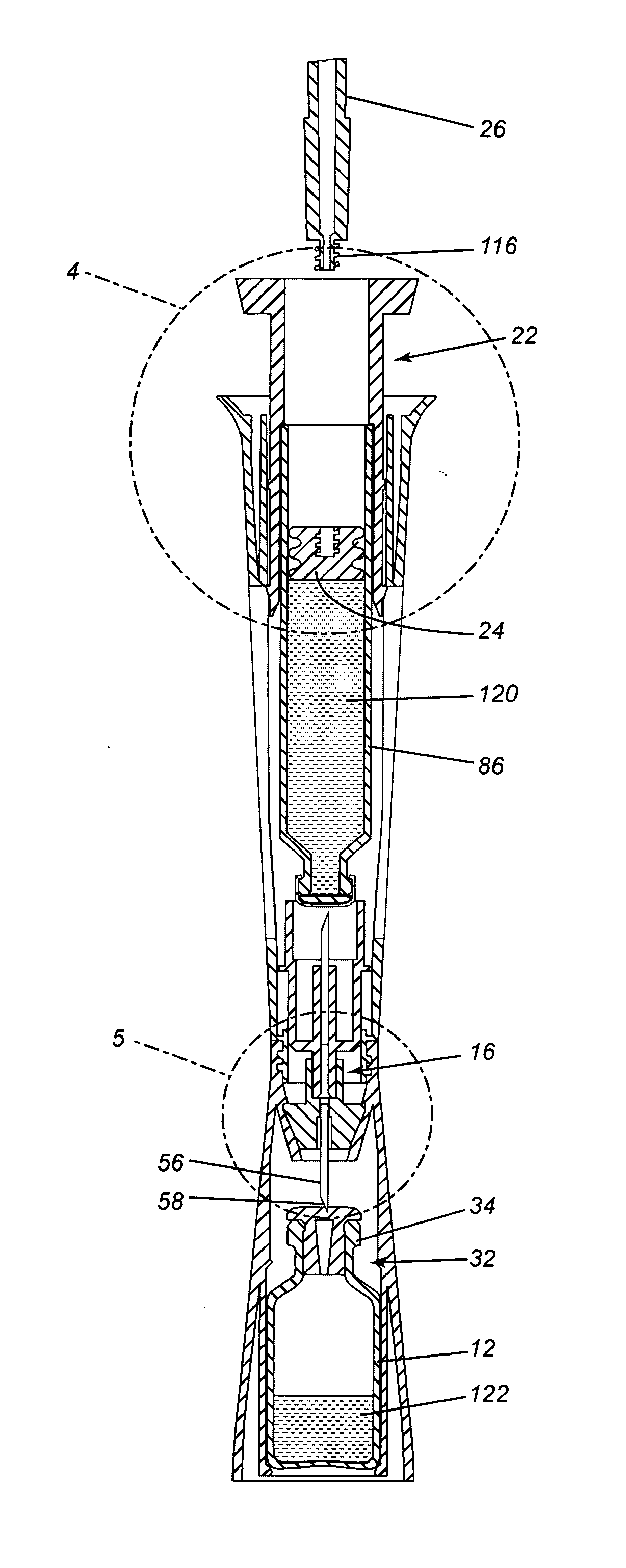
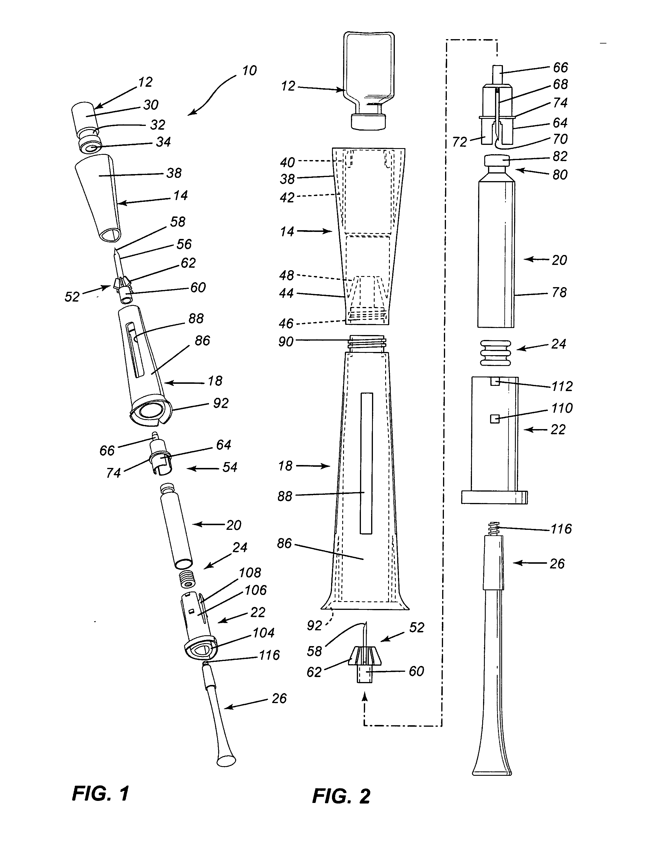
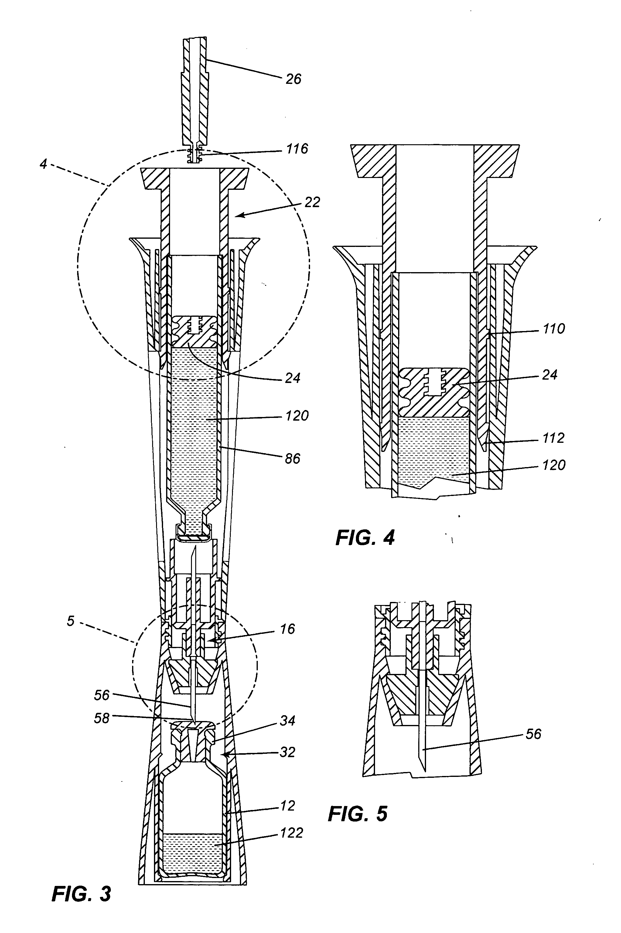
[0035]Referring to the drawings in greater detail and by reference characters thereto, there is illustrated a transfer system which is generally designated by reference numeral 10.

[0036]A vial generally designated by reference numeral 12 is associated with the transfer system which also includes a vial socket 14 designed to receive vial 12. Transfer system 10 also includes a needle hub generally designated by reference numeral 16 (FIG. 3). A housing 18 is designed to extend about a cartridge 20. The proximal end of transfer system 10 includes an activation cap 22. A plunger 24 is designed to fit within the open end cartridge 20 while a plunger rod 26 is engageable with plunger 24 as will be discussed hereinbelow.

[0037]In describing various components, the terms “proximal” and “distal” are utilized. In each instance, the term proximal refers to the end closest to the hand of the user while the term distal refers to the end furthest removed from the hand of the operator.

[0038]Vial 12 ...


PUM

PropertyMeasurementUnit
areasaaaaaaaaaa
volumeaaaaaaaaaa
compositionaaaaaaaaaa

Abstract

A transfer system suitable for medicaments comprising a vial socket, a housing having first and second open ends with the first open end being releasably connected to the vial socket, a needle hub mounted within the housing, a needle having first and second piercing ends mounted in the needle hub, a vial having a neck and a body, the vial being inserted in the vial socket and being non removably retained therein, a cartridge having a plunger sealing an open end thereof and a septum located at an opposite end of the cartridge, and an activation cap for causing the needle to penetrate a septum of the vial and the septum of the cartridge to permit transfer of components therebetween.

Description

[0001]The present invention claims priority on U.S. Application Ser. No. 61 / 280,169 filed Oct. 30, 2009.FIELD OF THE INVENTION[0002]The present invention relates to fluid transfer assemblies generally used for pharmaceutical delivery systems and to a method for reconstituting a pharmaceutical preparation.BACKGROUND OF THE INVENTION[0003]Traditionally, a pharmaceutical preparation has been dispensed using devices such as syringes. The syringe is usually filled manually by aspirating a liquid pharmaceutical component from a pharmaceutical vial having a neck with a penetrable closure into the syringe through a needle that penetrates the penetrable closure. The method of manually filling the syringe typically includes the steps of drawing air into the body of the syringe until the volume of air in the body approximately equals the volume of pharmaceutical component to be loaded into the syringe and subsequently inserting the needle through the penetrable closure into the vial.[0004]Many...

Claims


Application Information

Patent Timeline
Patent Type & Authority Applications(United States)
IPC IPC(8): A61J1/20
CPCA61J1/2096A61J2001/2055A61J2001/2065A61J2001/2013A61J1/2055A61J1/2013A61J1/1406A61J1/2089B65B3/003
Inventor REYNOLDS, DAVID L.MACDONALD, DANIELTREMBLAY, YAN
Owner DUOJECT MEDICAL SYSTEMS INC
Why Eureka
Try Eureka