Eureka AIR delivers breakthrough ideas for toughest innovation challenges, trusted by R&D personnel around the world.

Arrangement and Method for Controlling a Drive of an Automotive, Driverless Transportation Device

Inactive Publication Date: 2011-05-05
SIEMENS AG
View PDF11 Cites 2 Cited by
  • Summary
  • Abstract
  • Description
  • Claims
  • Application Information

AI Technical Summary

Benefits of technology

[0007]It is therefore an object of the present invention to provide a structurally simple and reliable controller for driverless transportation devices in such special fabrication areas.
[0009]The object is achieved, in particular, by an arrangement for controlling a drive of an automotive, driverless transportation device, where the drive of a driverless transportation device or the drives of a plurality of driverless transportation devices is or are controlled by a stationary control device. Here, a chain of light sources (segments), which comprises a running light, is arranged along a route of the driverless transportation device, where at least two optical sensors for sensing the running light are arranged one behind the other in the direction of movement on the driverless transportation device, where the at least two sensors are connected to the drive of the driverless transportation device such that the driverless transportation device essentially synchronously follows an illuminated segment of the running light, and where the stationary control device is configured to control the running light. With such an arrangement, significant savings can be obtained in system construction for arrangements with driverless transportation devices, such as in the fabrication of automobiles. Due to a relatively low outlay of electrical components, the requirement of additional drag chain conveyors is obviated. Additional unlocking and locking stations (coupling and decoupling stations) can also be eliminated. The technical complexity on the part of the driverless transportation device is also low since only the (usually binary) signals of the light sensors have to be evaluated. As a result, the use of simple controllers, such as simple “frequency converters” with binary auxiliary logic as vehicle controller, is possible.

Problems solved by technology

The technical complexity on the part of the driverless transportation device is also low since only the (usually binary) signals of the light sensors have to be evaluated.

Method used


Image

  • Arrangement and Method for Controlling a Drive of an Automotive, Driverless Transportation Device
  • Arrangement and Method for Controlling a Drive of an Automotive, Driverless Transportation Device
  • Arrangement and Method for Controlling a Drive of an Automotive, Driverless Transportation Device

Examples


Embodiment Construction

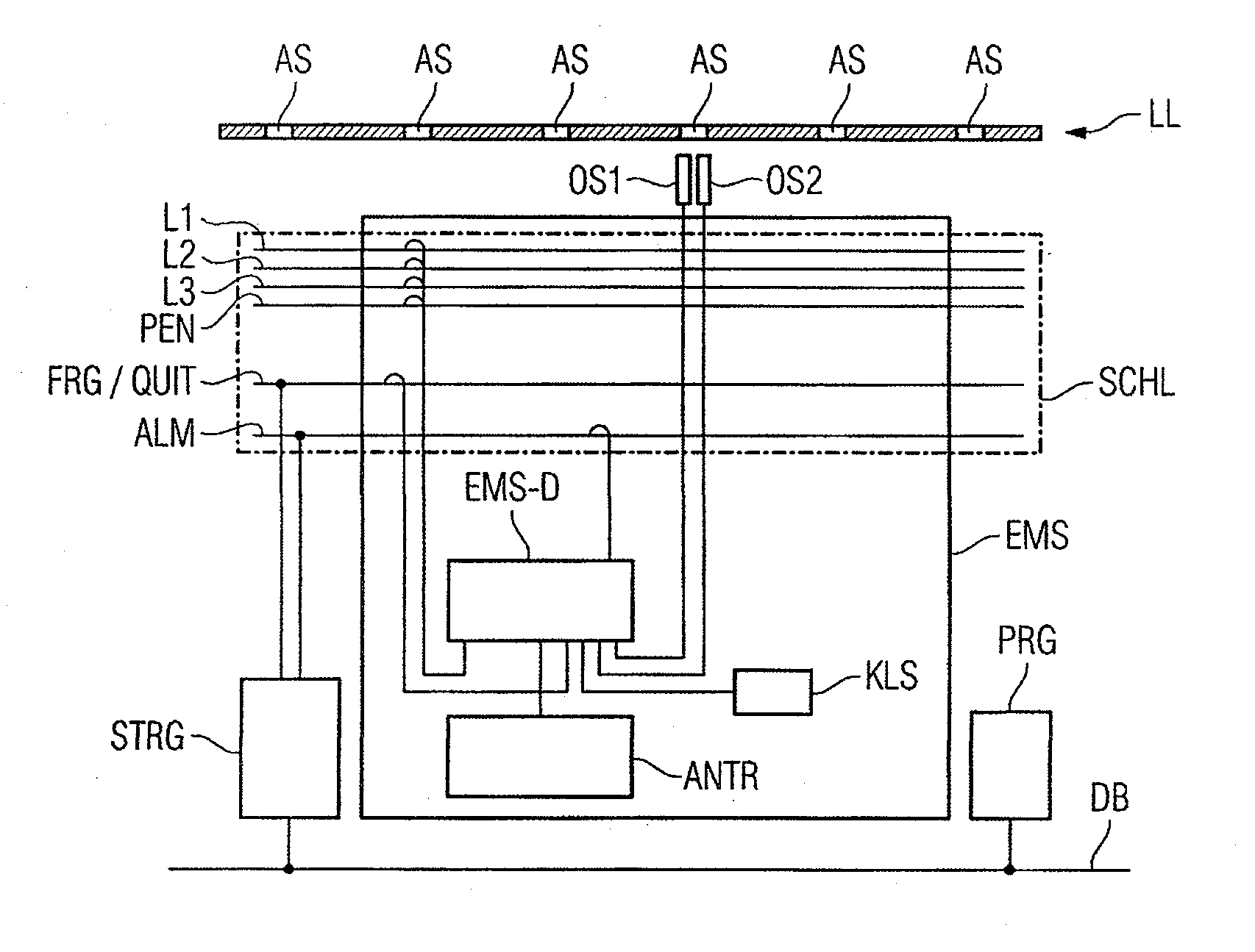
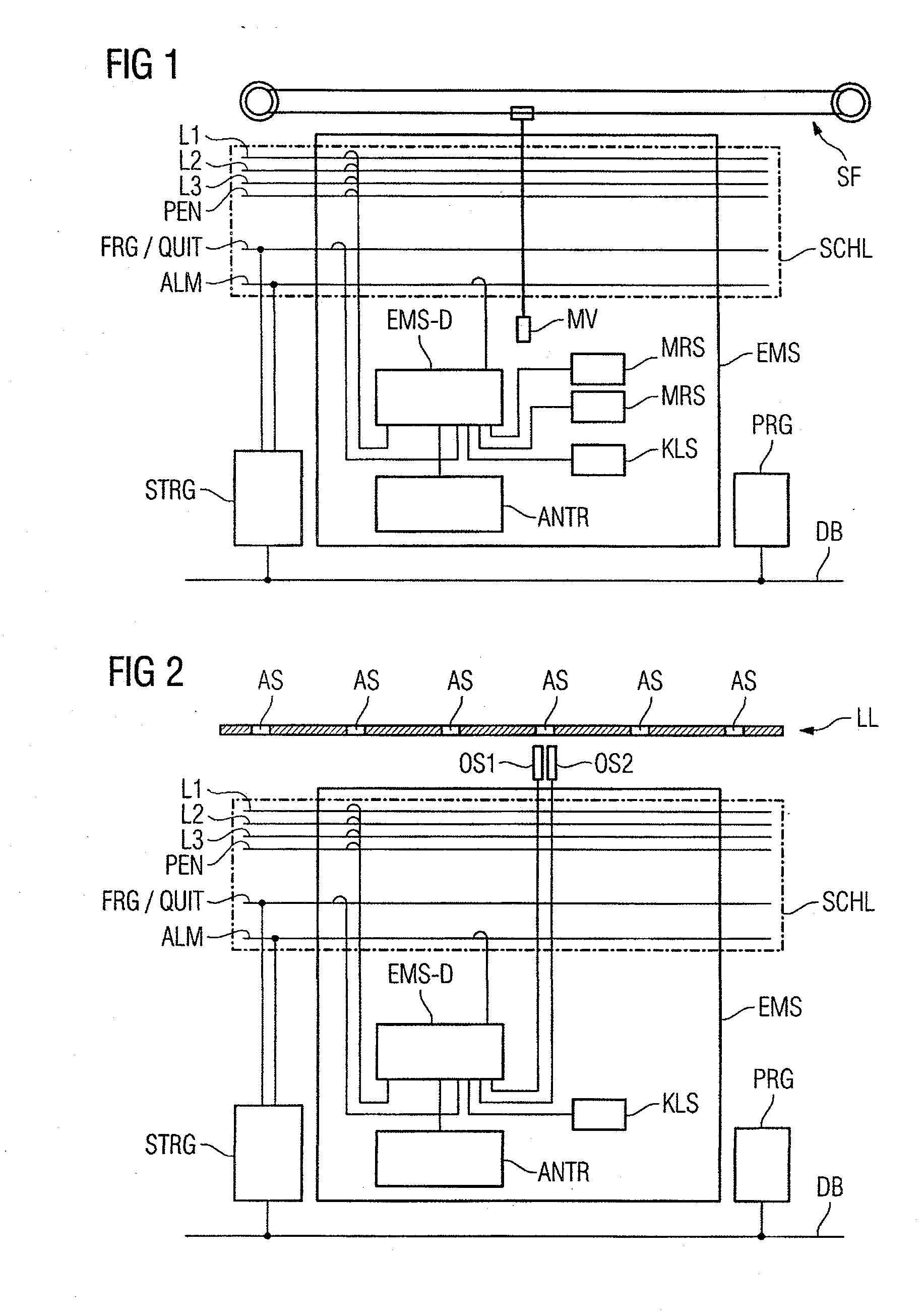
[0019]FIG. 1 is a schematic illustration of an automotive, driverless transportation device EMS (“electrical monorail system”) in an arrangement according to the prior art. Here, the transportation device EMS is connected by sliders (current collectors) to a stationary power rail system SCHL, which is equipped both with the conductors L1, L2, L3, PEN for supplying energy and with two further conductors FRG / QUIT (“enable” / “acknowledge”) and ALM (“alarm”). The stationary conductors of the power rail system SCHL are connected by sliding contacts to a controller EMS-D (“electrical monorail system-driver”) of the driverless transportation device EMS, which controller EMS-D in turn controls a drive ANTR of the transportation device EMS. In addition, the controller EMS-D is connected to the sensors MRS, KLS, where the sensors MRS (“magnetic incremental switch”) are activated by stationary activation devices (“cams”) on the route by movement of the transportation device EMS, and can easily ...


PUM


Abstract

An arrangement and a method for controlling a drive of an automotive, driverless transportation device, wherein the drive of a driverless transportation device or the drives of a plurality of driverless transportation device is or are controlled by means of a stationary control device. Here, a chain of light sources which is embodied as a running light is arranged along a route of the driverless transportation device, wherein at least two optical sensors for sensing the running light are arranged one behind the other on the driverless transportation device. The at least two sensors are connected to the drive of the driverless transportation device such that the driverless transportation device essentially synchronously follows at least one illuminated segment of the running light, and the stationary control device is configured to control the running light. As a result, it is possible to eliminate the mechanical drag chain conveyors.

Description

BACKGROUND OF THE INVENTION[0001]1. Field of the Invention[0002]The invention relates to an arrangement for controlling a drive of an automotive, driverless transportation device, and to a method for controlling the drive of the automotive, driverless transportation device.[0003]2. Description of the Related Art[0004]During progressive automization of transportation tasks, i.e., in the field of fabricating automobiles and other goods, use is frequently made of driverless transportation devices. For example, electric overhead tracks (EHB), a telpher system, are used for transporting vehicle bodies and attachment parts in manufacturing lines of the automobile industry. These transportation devices or electrical monorail systems (EMS) are generally composed of a rail system and associated, usually suspended, vehicles. These transportation devices have their own electric drive and are supplied with electrical energy by current collectors (sliders) which are guided along a multi-phase po...

Claims


Application Information

Patent Timeline
IPC IPC(8): G05D1/00
CPCB61L27/04B61L23/18
Inventor MULLER, OSWALD
Owner SIEMENS AG
Why Eureka
Eureka Blog
Learn More