
User interface for monitoring the status of medical machines

a technology user interfaces, which is applied in the field of user interfaces for monitoring the status of medical machines, can solve the problems of difficulty in managing interventions, difficulty in evaluating the exact functioning of each of the machines, and the number of alarms and signallings, and achieve the effect of good overall functioning of the medical devi

Inactive Publication Date: 2011-05-05
GAMBRO LUNDIA AB
View PDF12 Cites 97 Cited by
  • Summary
  • Abstract
  • Description
  • Claims
  • Application Information

AI Technical Summary

Benefits of technology

[0018]A further aim of the invention is to provide the technician with data relating to the reliability of a single medical machine over a period of time, thus in particular providing data relating to the present moment and data relating to the past, and also providing the possibility of having available the detailed data relating to the machine itself or particular parameters of interest.
[0019]A further auxiliary aim of the invention is to provide a graphic user interface which enables good overall functioning of the medical device, i.e. the critical level of the overall machine status, independently of the single parameter or the plurality of parameters in the alarm state.

Problems solved by technology

Firstly the cited management systems perform their function very well only in the presence of a single monitored machine, or in any case having a small number of such devices.
In the presence of a large number of machines, for example connected in a network internally of a clinic, the number of alarms and signallings can be quite high, which leads to a difficulty in managing the interventions, even where the priority codes enable a first evaluation of the most urgent operations to be carried out.
In this way it is very difficult to evaluate the exact functioning of each of the machines, both in a determined moment and during the course of functioning of the machine itself over time.
Last but not least, it is worthy of note that there is also a difficulty in interpreting the data presented by the graphic user interface rapidly, in particular excluding the data which is not of importance during the consultation and viewing only the data which is of interest.

Method used


Image

  • User interface for monitoring the status of medical machines
  • User interface for monitoring the status of medical machines
  • User interface for monitoring the status of medical machines

Examples


Embodiment Construction

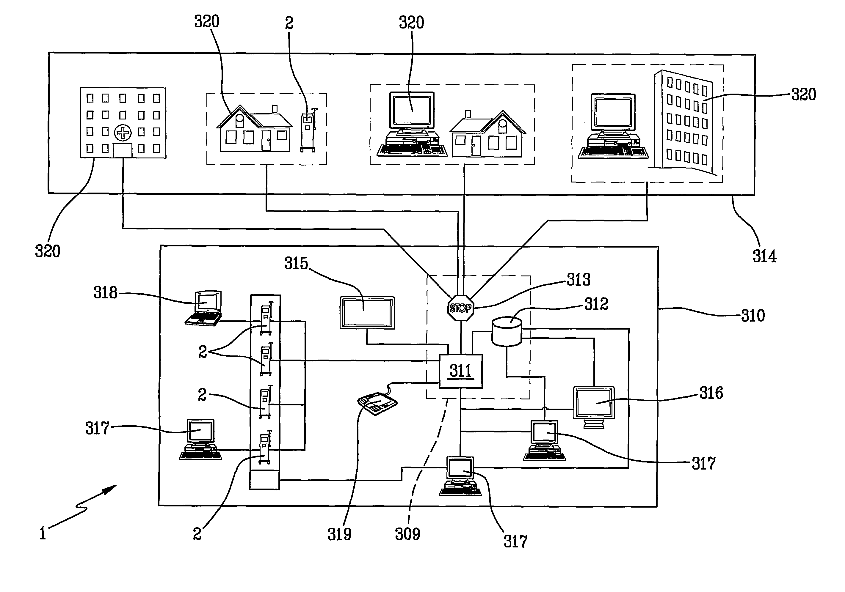
[0029]FIG. 1a is a schematic view of a medical network which internally comprises the object of the present invention.

[0030]The inset shows an example of a first portion 310 of the medical network 1 delimiting the equipment of the network which is typically present internally of a same building such as a hospital, a dialysis unit, or a clinic.

[0031]In the first portion 310 of network there is especially the presence of a plurality of medical machines 2 and in particular medical machines 2 suitable for treatment of fluids.

[0032]Medical machines 2 are in general all connected to one another and to a central server 309.

[0033]The central server 309 is constituted by at least a server computer 311 (also known as a FAM), a database 312 and special means for access 313 to the external portion 314 of the medical network 1.

[0034]As can be observed, once more schematically, there is at least one (and in general a plurality) of terminals for visual access 316 to enable personnel (in particular...


PUM


Abstract

A user interface for monitoring the status of medical machines includes a display which shows data coming from a processing unit relating to parameters of the machines. The processing unit comprises means for establishing to which operating status of the medical machines the data belongs to. The processing unit determines if a medical machine is in correct functioning status; if a medical machine is in a warning status; or if a machine is in critical status. Means generate synthetic data characterised using colours according to whether the medical machine is in the correct functioning, the warning or the critical status.

Description

BACKGROUND OF THE INVENTION[0001]The invention relates to a user interface for monitoring a status of medical machines and in particular a graphic user interface which enables immediate and intuitive viewing of the machine status and management of the alarms of a plurality of medical machines, for example machines for extracorporeal treatment of a fluid, for example a patient's blood, making part of a data network of medical machines, which might be a clinic or hospital network.[0002]As is known, medical machines, such as for example machines for treatment of kidney failure or liver insufficiency or machines for plasmapheresis, i.e. machine for other types of fluid treatment are provided with an adequate graphic user interface for enabling correct monitoring of the functioning of the machine, the treatment functions underway, i.e. the parameters of the data detected and sent by the sensors and actuators which enable the treatment.[0003]In general all the above-mentioned machines are...

Claims


Application Information

Patent Timeline
IPC IPC(8): G06F3/048G16H40/40
CPCG06F19/3418G16H40/40
Inventor GUAITOLI, GIULIOSTEFANINI, MICHELEORLANDI, LORENZO
Owner GAMBRO LUNDIA AB
Learn More