Oscillating rod cutter

Inactive Publication Date: 2011-05-12
VERMONT INSTR MAKERS
View PDF5 Cites 14 Cited by
  • Summary
  • Abstract
  • Description
  • Claims
  • Application Information

AI Technical Summary

Benefits of technology

[0007]The present disclosure provides a rod cutter which produces forces sufficient to cut durable rods such as rods made of titanium, and which does not require a cumbersome base or mount. The rod cutter employs a series of gears, eccentric members and plate members that drive a circular blade to oscillate relative to a rod to be cut. The oscilla

Problems solved by technology

Spinal implants involve the use of rods, which are typically too long and need to be cut down to fit individual needs.
Due to the use of leverage as the cutting force, such as with conventiona

Method used


Image

  • Oscillating rod cutter
  • Oscillating rod cutter
  • Oscillating rod cutter

Examples


Embodiment Construction

[0027]The invention relates to an apparatus for cutting rods, and more particularly to an apparatus which utilizes an oscillating blade to cut rods which can be otherwise difficult to cut, such as titanium rods used in surgical procedures.

[0028]Hereinafter the term “rod” is used to refer to any one or all of the following terms: metal rod, plastic rod, an article of the appropriate size and shape, i.e. an elongated member and any article that may benefit from or be cut by this novel rod cutter.

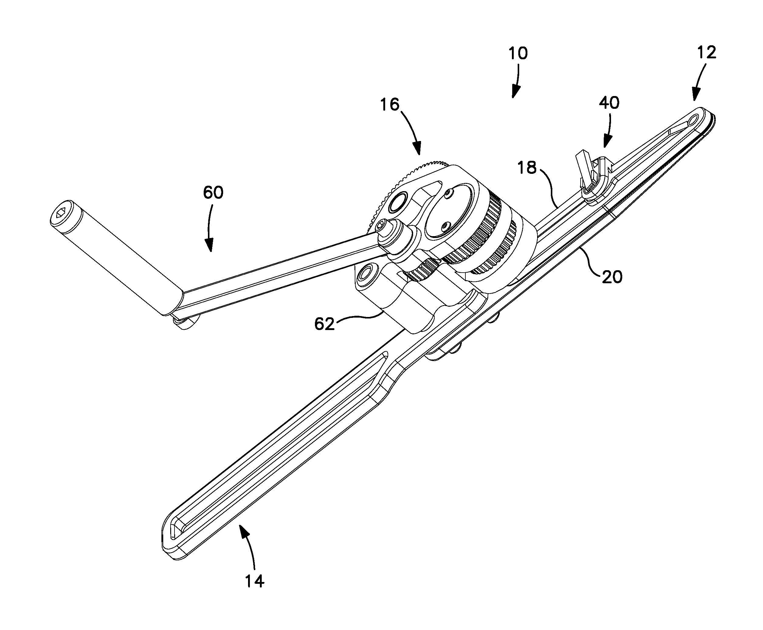
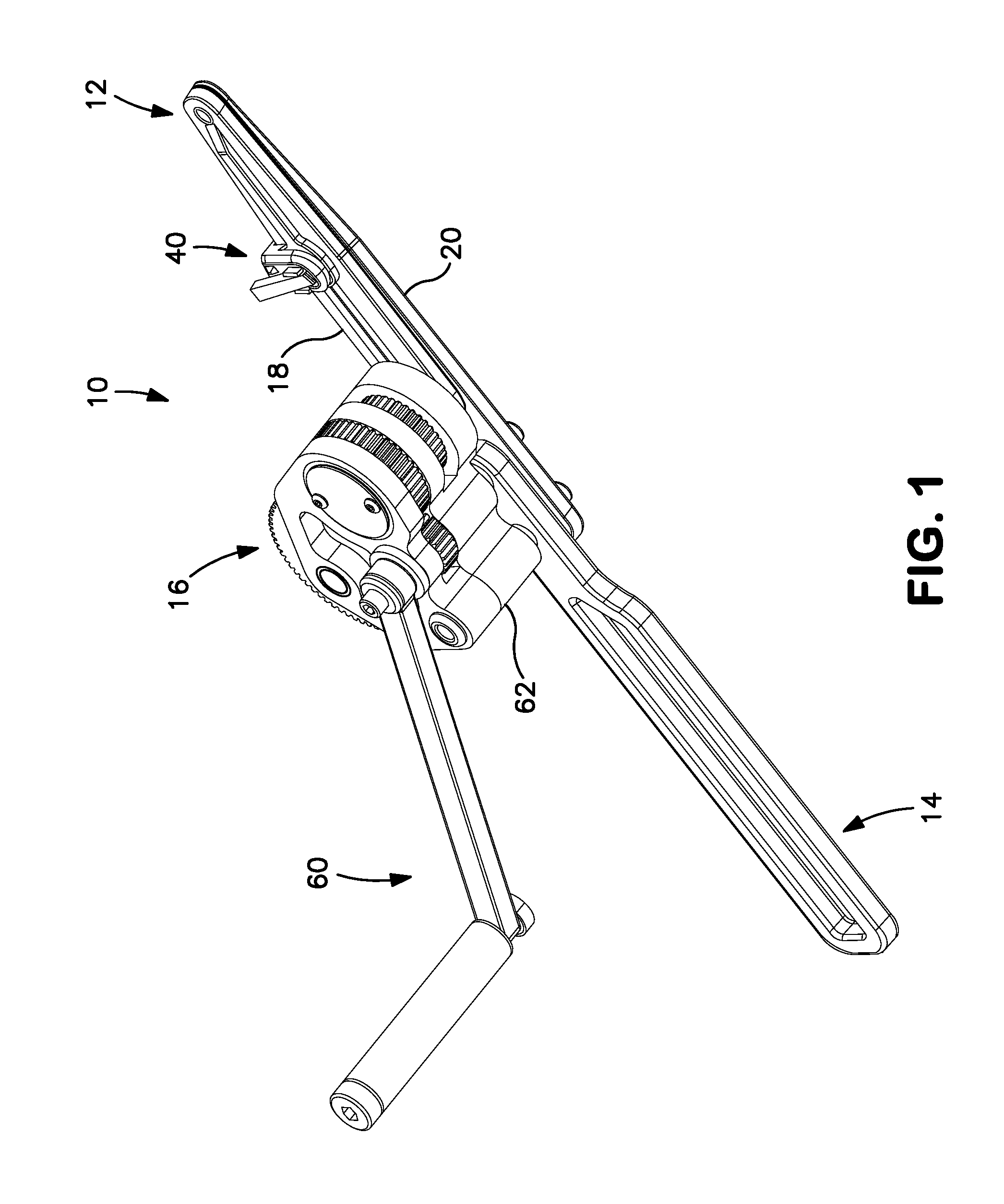
[0029]FIG. 1 illustrates a rod cutter apparatus 10 according to the invention which will be referred to herein as rod cutter 10 or apparatus 10. Rod cutter 10 according to the invention has a cutting assembly 12 for holding and cutting a rod, a handle 14 and a drive assembly 16 for driving movement of a cutting blade relative to a rod held in cutting assembly 12 as will be discussed further below.

[0030]Also as will be further discussed below, rod cutter 10 cuts rods by generating an oscillatin...


PUM

PropertyMeasurementUnit
Radiusaaaaaaaaaa
Diameteraaaaaaaaaa

Abstract

A rod cutter apparatus includes a rod holding plate having a rod opening for receiving a rod to be cut; a cutting member having a central opening defined by a cutting edge, the central opening being substantially aligned with the rod opening; and a drive assembly connected between the rod holding plate and the cutting member to cause oscillation of the cutting member relative to the rod holding plate, wherein oscillation of the cutting member relative to the rod holding plate cuts a rod in the rod opening.

Description

CROSS-REFERENCE TO RELATED APPLICATION[0001]This application claims the benefit of the filing date of U.S. Provisional Application 61 / 259,253, filed Nov. 9, 2009.BACKGROUND OF THE INVENTION[0002]This invention relates to a device for cutting rods, more particularly, to a rod cutter that is useful in cutting rods that are used in the medical arts. These rods may be the implanting rods, such as but not limited to, rods implanted or implantable in a body for spinal fixation, bone fixation and the like.[0003]Spinal implants involve the use of rods, which are typically too long and need to be cut down to fit individual needs. Rod cutters may be used for this purpose and are typically arranged to have a supporting base that rests upon a tabletop or the like, and a relatively long handle is pivoted to the base for actuating cutters, which sever a rod to be used in the spinal implant. In that endeavor, the goal is to provide a rod cutter with sufficient mechanical advantage or cutting lever...

Claims


Application Information

Patent Timeline
IPC IPC(8): B23D17/04B23D29/00B26D3/16
CPCA61B17/8863B26D3/16B23D29/023Y10T83/04
Inventor CRAINICH, LAWRENCETRABKA, JOSEPH E.
Owner VERMONT INSTR MAKERS
Why Eureka
Try Eureka