Cutter for machining Fresnel patterns and manufacture method of cutter

A manufacturing method and pattern technology are applied to the tool for processing Fresnel pattern and its manufacturing field, which can solve the problems of high processing difficulty, low processing efficiency, difficult burden, etc., and achieve the improvement of the sharpness of the blade, the improvement of the quality of the pattern, and the improvement of fineness. degree of effect

Active Publication Date: 2015-07-08
DATAMATIC GUANGZHOU INJECTION MOLD
View PDF8 Cites 0 Cited by
  • Summary
  • Abstract
  • Description
  • Claims
  • Application Information

AI Technical Summary

Problems solved by technology

Each processing method has its own limitations. (1) Photolithography: Due to the limitation of the depth of field, it is limited to the processing of two-dimensional structures and small aspect ratio three-dimensional structures; (2) using sacrificial layer etching technology, although Quasi-three-dimensional processing can be realized, but it is easy to cause internal stress in the material and affect the final mechanical properties, and the etching technology is affected by the crystal orientation of the material, the processing accuracy is poor, and the quality of the processed surface is poor; (3) LICA technology: LIGA technology must use expensive , The cost of the rare high-collimation X-ray light source is much higher than that of lithography equipment, and it is difficult for general laboratories and enterprises to afford it. At the same time, in principle, it is difficult for LIGA process Machining 3D structures
However, other micro-manufacturing technologies, such as deposition, are generally planar processes, which are difficult to adapt to the processing of three-dimensional structures.
(4) Electron beam writing and laser beam writing technologies are inefficient and difficult to mass produce; (5) Replication technology, including thermocompression molding, compression molding and injection molding, is a low-cost method suitable for mass production. (6) High-speed milling technology, which has high machining accuracy, but it is powerless to process the sharp corners of the tooth shape, and will produce a natural processing fillet slightly larger than the radius of the tool. Theoretically, the smaller the tool, the smaller the processing fillet, but the smaller the tool, the more difficult it is to process, the smaller the tool rigidity, the lower the processing efficiency, the shorter the cutting life of the tool, and the higher the processing cost

Method used


Image

  • Cutter for machining Fresnel patterns and manufacture method of cutter
  • Cutter for machining Fresnel patterns and manufacture method of cutter
  • Cutter for machining Fresnel patterns and manufacture method of cutter

Examples


Embodiment 1

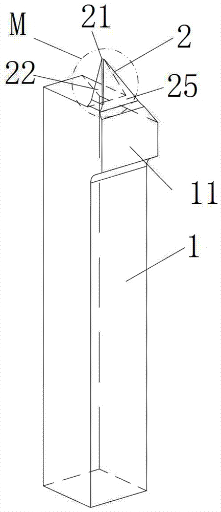
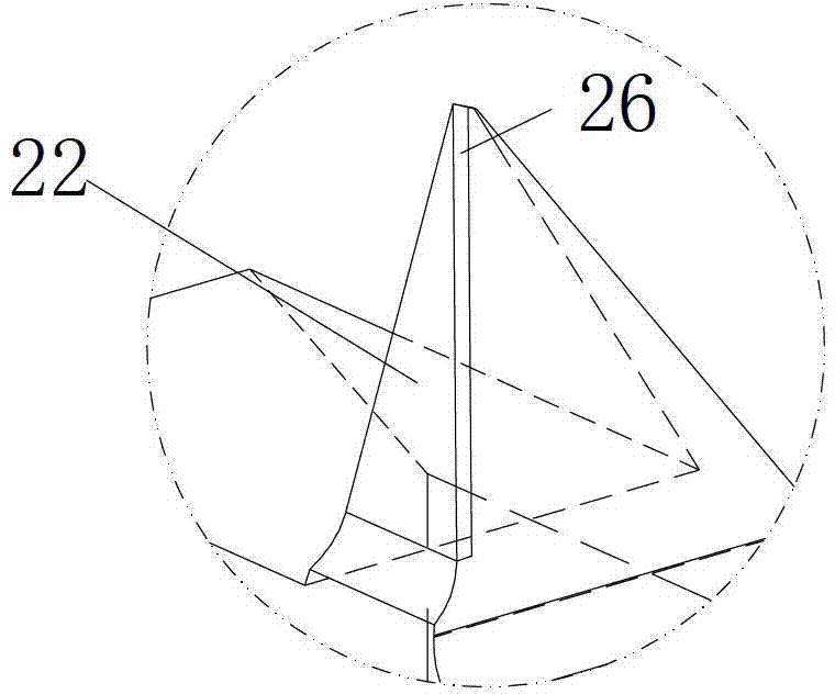
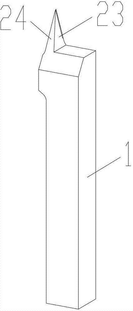
[0035] Embodiments of the present invention provide a tool for processing Fresnel patterns, such as Figure 1 to Figure 7Shown, comprise cutter bar 1 and be located at the cutter head 2 above cutter bar 1, described cutter head 2 is the cone with four sidewalls, and this cone apex is the cutter tip 21 of cutter head, and the cutter head 2 of this cone The four side walls are respectively the rake face 22, the flank face 23, the auxiliary flank face 24 and the side cutter face 25 of the cutter head, the rake face 22 is facing the auxiliary flank face 24, and the flank face 23 is facing the side cutter Surface 25; the surface of the rake face 22 is inlaid with a layer of diamond 26 with a thickness of 0.2 mm to 0.8 mm. In the embodiment of the present invention, the thickness of the diamond is 0.5 mm, so that the cost of the cutter head and the hardness of the cutter head are optimized. Diamonds can be natural diamonds and artificial diamonds. From the perspective of enhancing p...

Embodiment 2

[0057] An embodiment of the present invention provides a method for manufacturing a tool for processing a Fresnel pattern to realize the manufacturing of the tool described in Embodiment 1 above, and the method includes the following steps.

[0058] Step 100: Obtain the parameter r of the Fresnel pattern to be processed min , R min , A max and alpha min . In this step, according to the parameters of the Fresnel pattern to be processed, a limit tooth space is assumed, and the limit tooth space contains the above-mentioned parameter r min , R min , A max and alpha min , so as to facilitate the later trimming design and processing.

[0059] Step 101: Machining a cylinder blank. In this step, the raw material of the tool is preliminarily processed, and the raw material is processed into a cylinder blank, which can be a cylinder or a square column. In order to facilitate later operations, the raw material is processed into a square cylinder blank in the embodiment of the pr...


PUM

PropertyMeasurementUnit
thicknessaaaaaaaaaa
thicknessaaaaaaaaaa

Abstract

The invention discloses a cutter for machining Fresnel patterns and a manufacture method of the cutter. A cutter bit of the cutter is a cone with four side walls, a diamond layer with the thickness of 0.2-0.8mm is embedded on the surface of a front cutter face, the front cutter face and side cutter faces incline towards the inner side of the cutter bit from top to bottom to respectively form a first negative deflection angle and a second negative deflection angle together with a vertical line passing through the cutter bit; an auxiliary rear cutter face is formed by linking a first incline and a second incline with different slopes from the cutter bit to the root part of the cutter bit; and the bottom edge of a rear cutter face inclines towards the side cutter faces from the front cutter face to the auxiliary rear cutter face to form a rear cutter face inclination angle. According to the cutter, the strength of the cutter bit is greatly improved, the front cutter face and the side cutter faces incline towards the inner side for a certain angle, the negative deflection angle of the front cutter face is capable of well discharging cuttings, the negative deflection angles of the side cutter faces are capable of avoiding a machining material, thus the refining degree of machined patterns is improved; and the auxiliary rear cutter face is capable of ensuring that a machined face of a workpiece is not touched in a machining process, and thus the quality of the machined patterns is further improved.

Description

technical field [0001] The invention relates to the technical field of optical elements, in particular to a tool for processing Fresnel patterns and a manufacturing method thereof. Background technique [0002] Fresnel micro-optical structural elements have the characteristics of small size, light weight, and easy integration. They have broad application prospects in military and civilian industries. At present, their processing methods include electron beam writing technology, laser beam writing technology, photolithography technology, Etching technology, deposition and image etching technology, LIGA technology, replication technology, coating technology and high-speed milling technology, etc. Each processing method has its own limitations. (1) Photolithography: Due to the limitation of the depth of field, it is limited to the processing of two-dimensional structures and small aspect ratio three-dimensional structures; (2) using sacrificial layer etching technology, althoug...

Claims


Application Information

Patent Timeline
Patent Type & Authority Patents(China)
IPC IPC(8): B23C5/02B23P15/34
Inventor 彭康勇
Owner DATAMATIC GUANGZHOU INJECTION MOLD
Why Eureka
Try Eureka