A high wear resistance shield machine hob ring

A high wear resistance, shield machine technology, applied in mining equipment, tunnels, earthwork drilling and mining, etc., can solve the problems of hard alloy block wear, uneven hob wear, hard alloy block loosening, etc. Achieve the effects of improving wear resistance and service life, enhancing overall service life, and enhancing overall wear resistance

Active Publication Date: 2019-10-29
ANHUI LINGFENG METALLURGICAL MACHINERY
View PDF6 Cites 0 Cited by
  • Summary
  • Abstract
  • Description
  • Claims
  • Application Information

AI Technical Summary

Problems solved by technology

This application can increase the speed of excavation, reduce the wear of the tool and increase the service life of the tool, but the structure of the application is complex, the production process is difficult, and the production cost is high
[0004] Another example is the Chinese patent application number: 201620936968X, application date: August 25, 2016, the name of the invention is: a shield machine hob, the application discloses a shield machine hob, hob An annular groove is arranged on the outer circumference of the body, a through hole is arranged on one side wall of the annular groove, and a corresponding blind hole is arranged on the other side wall; The alloy block is provided with a mounting hole corresponding to the through hole; a connecting bolt is provided in the through hole, and the connecting bolt passes through the through hole and the mounting hole and is inserted into the blind hole; the application can theoretically realize the quick disassembly of the cemented carbide block It can reduce the overall replacement of the cutter ring, but the wear force of the cutter ring is extremely high in actual use, and it is difficult to effectively fix the cemented carbide block through bolt cooperation, and it is easy to cause the cemented carbide block to loosen in engineering practice. It is easy to cause greater wear to the cemented carbide block, and also affects the normal excavation and use of the cutter ring, making it difficult to use in practice
[0005] Another example is the Chinese patent application number: 2010205107727, application date: August 26, 2010, and the name of the invention is: hob hob for shield machine. A hard alloy rolling ring is brazed on the circumference, and the rolling ring is composed of a plurality of arc-shaped bars, which are brazed in the annular inner groove of the ring body; the two lateral sides of each arc-shaped bar are respectively provided with convex The longitudinal ribs raised; this application is convenient for brazing, and the brazing is firm, but this application can only strengthen the outermost strength of the cutter ring, and the hob ring is prone to uneven wear and inconsistent rock-breaking effects during use, which affects Stable use of tools
[0006] To sum up, in the prior art, the method of adding cemented carbide outside the cutter ring is widely used to enhance the wear resistance of the cutter ring and improve the service life of the hob ring, but the specific setting methods of the cemented carbide vary widely. There are also advantages and disadvantages in the use performance of shield cutters. How to reasonably set up cemented carbide on the basis of cost control, and use the high strength of cemented carbide to effectively improve the wear resistance of shield cutter rings has become an unswerving pursuit in the industry.

Method used


Image

  • A high wear resistance shield machine hob ring
  • A high wear resistance shield machine hob ring
  • A high wear resistance shield machine hob ring

Examples


Embodiment 1

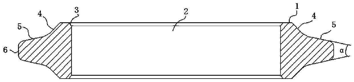
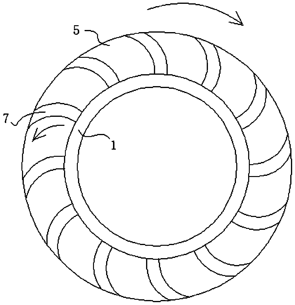
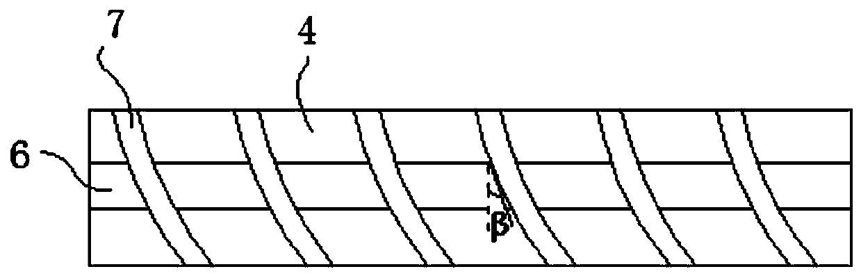
[0037] like Figure 1-Figure 3 As shown, a hob ring of a shield machine with high wear resistance in this embodiment includes a cutter ring body 1, and an installation cavity 2 is opened in the cutter ring body 1, and the hob ring is installed through the installation cavity 2 in actual use. On the central power shaft, it is used to drive the rotation and feed of the hob ring, and the first and last ends of the installation cavity 2 are provided with inclined inner walls 3 with openings gradually enclosing outwards along the circumferential direction, such as figure 1 As shown, the setting of the inclined inner wall 3 facilitates the installation and positioning of the hob ring and the central power shaft. Further, the inner wall of the installation cavity 2 is an inclined inner wall, and the included angle with the vertical direction is 1°-2° ( figure 1 (not marked in the middle), form the slope fit between the installation cavity 2 and the central power shaft, improve the fi...

Embodiment 2

[0048] A high wear resistance shield machine hob ring in this embodiment is basically the same as in Embodiment 1, the difference is that the thickness of the hard alloy in this embodiment is 4mm, and the surface of the hard alloy is respectively higher than the longitudinal transition Section 4, the transverse transition section 5 and the surface 1mm of the frontal area 6; the angle α between the tangents of the transverse transitional section 5 on both sides of the frontal area 6 is 24° in the present embodiment, and the arc-shaped cemented carbide is in the frontal area 6 The angle β between the tangent line at its top and the vertical plane is 15°.

Embodiment 3

[0050] A high wear resistance shield machine hob in this embodiment is basically the same as in Embodiment 1, the difference is that the thickness of the hard alloy in this embodiment is 3.5mm, and the surface of the hard alloy is respectively higher than the longitudinal The surface of the transition section 4, the transverse transition section 5, and the front area 6 is 0.5mm; in this embodiment, the angle α between the tangents of the transverse transition section 5 on both sides of the front area 6 is 26°, and the arc-shaped hard alloy is on the front side The angle β between the tangent line at the top of the area 6 and the vertical plane is 20°.


PUM


Abstract

The invention discloses a high abrasion resistance shield tunneling machine rolling cutter ring, and belongs to the field of shield tools. The high abrasion resistance shield tunneling machine rollingcutter ring comprises a cutter ring body, a mounting cavity is formed in the cutter ring body, and a front side area protruding outwards is arranged in the middle of the outer side of the cutter ringbody in the circumferential direction in a surrounding mode; annularly-distributed transverse transition sections are symmetrically arranged on the upper side and the lower side of the front side area, the transverse transition sections are connected with the cutter ring body through annularly-distributed longitudinal transition sections, fixing grooves are evenly formed in the annular side wallsof the longitudinal transition sections, and the transverse transition sections and the front side area at intervals correspondingly; and the fixing grooves in the longitudinal transition sections, the transverse transition sections and the front side area are connected in a one-to-one correspondence mode, and the fixing grooves are internally provided with hard alloys. According to the high abrasion resistance shield tunneling machine rolling cutter ring, by reasonably arranging the hard alloys on the outer side of the shield cutter ring, abrasion resistance of the cutter ring is effectivelyenhanced, the service life of the shield cutter ring is prolonged, the production cost is reduced, and the production loss is reduced.

Description

technical field [0001] The invention relates to the technical field of shield boring tools, in particular to a hob ring of a shield boring machine with high wear resistance. Background technique [0002] The construction of shield tunnel boring machine (referred to as shield machine) has the advantages of high degree of mechanization, fast construction speed, and high safety. It is widely used in large-scale construction projects such as mines, railways, and highways. The main tool for rock-breaking excavation is the key and vulnerable part of the shield machine. The hob cutter ring is always in contact with the rock during the entire excavation process. It is the working edge of excavation and rock breaking. It not only bears the huge thrust from the shield machine, but also withstands the severe wear of various hard substances in the rock. , resulting in serious wear of the cutter ring, the cutter ring must be replaced frequently, and the consumption is large, which reduc...

Claims


Application Information

Patent Timeline
Patent Type & Authority Patents(China)
IPC IPC(8): E21D9/08
CPCE21D9/08
Inventor 刘道豹刘威刘国庆
Owner ANHUI LINGFENG METALLURGICAL MACHINERY
Why Eureka
Try Eureka