Fuel injection apparatus

a technology of fuel injection apparatus and fuel injection tube, which is applied in the direction of liquid fuel feeders, combustion air/fuel air treatment, machines/engines, etc., can solve the problems of unstable assembly, difficult to assemble the sub-assembly and difficult to assemble to the plural throttle body. , to achieve the effect of improving reliability, simplifying the support structure, and facilitating assembly

Inactive Publication Date: 2011-05-12
MIKUNI CORP
View PDF8 Cites 5 Cited by
  • Summary
  • Abstract
  • Description
  • Claims
  • Application Information

AI Technical Summary

Benefits of technology

[0018]According to the fuel injection apparatus, since the passage of fuel flowing through the upstream side injector and the downstream side injector is bifurcated at the inside of the connecting pipe, the upstream side injector, the downstream side injector and the connecting pipe can be previously assembled to be a subassembly. Accordingly, since the subassembly can be assembled to the throttle body for each intake passage, the assembling becomes facilitated. Then, since the fuel supply pipe supports only the connecting pipe, the support structure is simplified and reliability thereof is improved.
[0019]Next, since the direction of the downstream side branch passage in the connecting pipe is set to be more to the downstream side than the direction of the upstream side injector, in other words, to be closer toward the combustion chamber and the direction of the downstream side injector is set to be more to the downstream side than the direction of the downstream side branch passage, the direction of the downstream side injector can be set to be closer toward the combustion chamber of the engine being more to the downstream side than the direction of the upstream side injector. Here, since the angle between the upstream side injector and the downstream side injector is dependent to the angle of bifurcation within the connecting pipe as well as the angle of connection from the connecting pipe to the downstream side injector, the angle between the upstream side injector and the downstream side injector can be enlarged while suppressing the respective angles of the bifurcation and connection. Accordingly, fuel can be injected to a position close to the combustion chamber and injected fuel can be supplied to the combustion chamber more efficiently.
[0020]Further, since the angle between the upstream side injector and the downstream side injector is dependent to the angle of bifurcation within the connecting pipe 6 in addition to the angle of connection from the connection pipe to the downstream side injector, the distance between the downstream side injector and the upstream side injector can be shortened. Accordingly, even with the fuel injection apparatus having fuel supplied to the two injectors with the common fuel supply pipe, fuel can be injected to a position close to the combustion chamber of the engine while suppressing the length of the throttle body in the intake flow direction.

Problems solved by technology

In that case, since the insertion direction of the downstream side injector is to be close to the direction perpendicular to the assembling direction of the fuel supply pipe, there is a fear that the assembling becomes unstable.
Here, in the case that the upstream side injectors and the downstream side injectors are previously assembled to the fuel supply pipe as sandwiching the respective connecting pipes to be a subassembly, it becomes difficult to assemble the subassembly to the plural throttle bodies.
Meanwhile, in the case that the upstream side injector, the downstream side injector having the connecting pipe, and the fuel supply pipe are to be assembled sequentially to the throttle body, it is difficult to assemble to the plural throttle bodies.

Method used


Image

  • Fuel injection apparatus
  • Fuel injection apparatus
  • Fuel injection apparatus

Examples


Embodiment Construction

[0027]Reference will now be made in detail to embodiments, examples of which are illustrated in the accompanying drawings, wherein like reference numerals refer to like elements throughout.

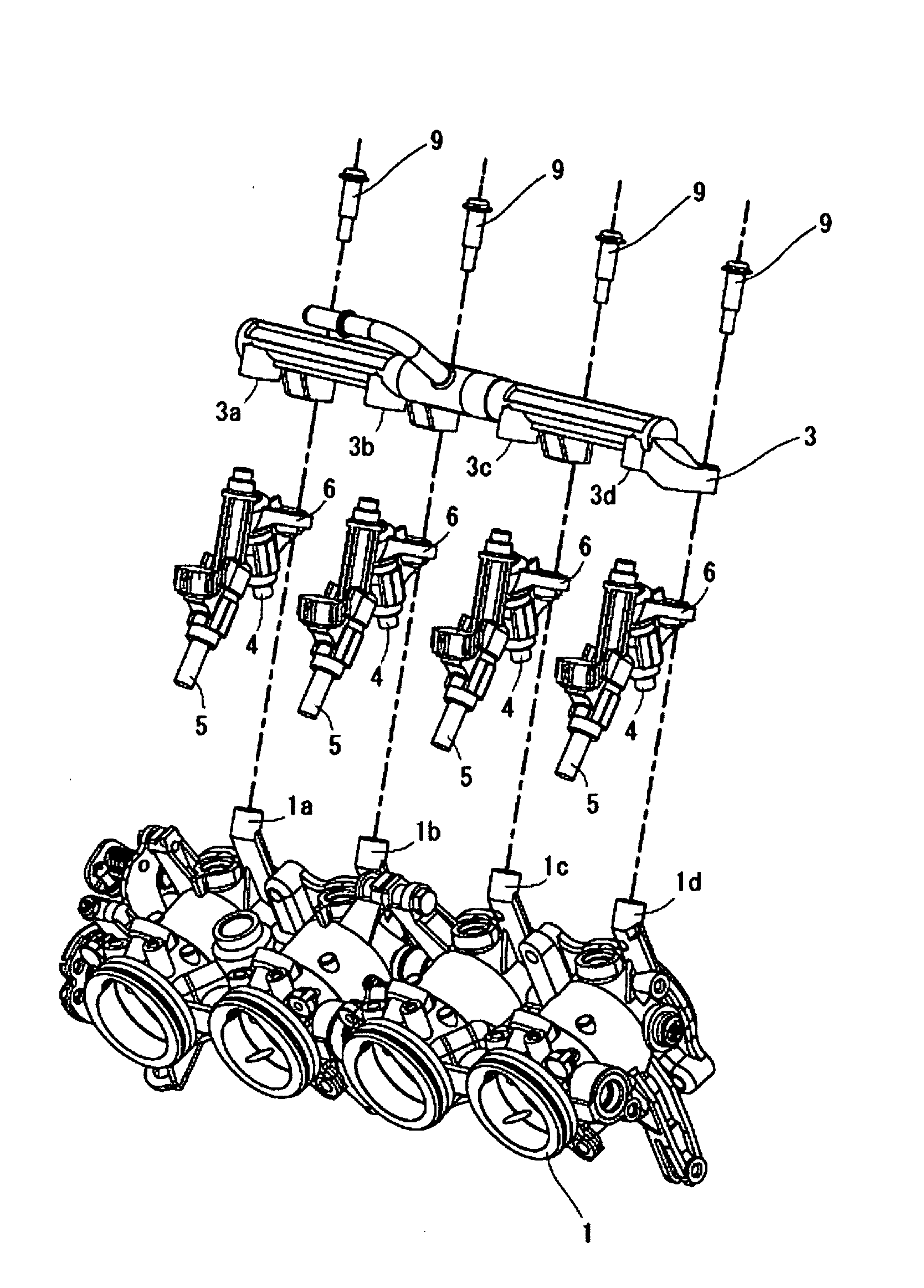
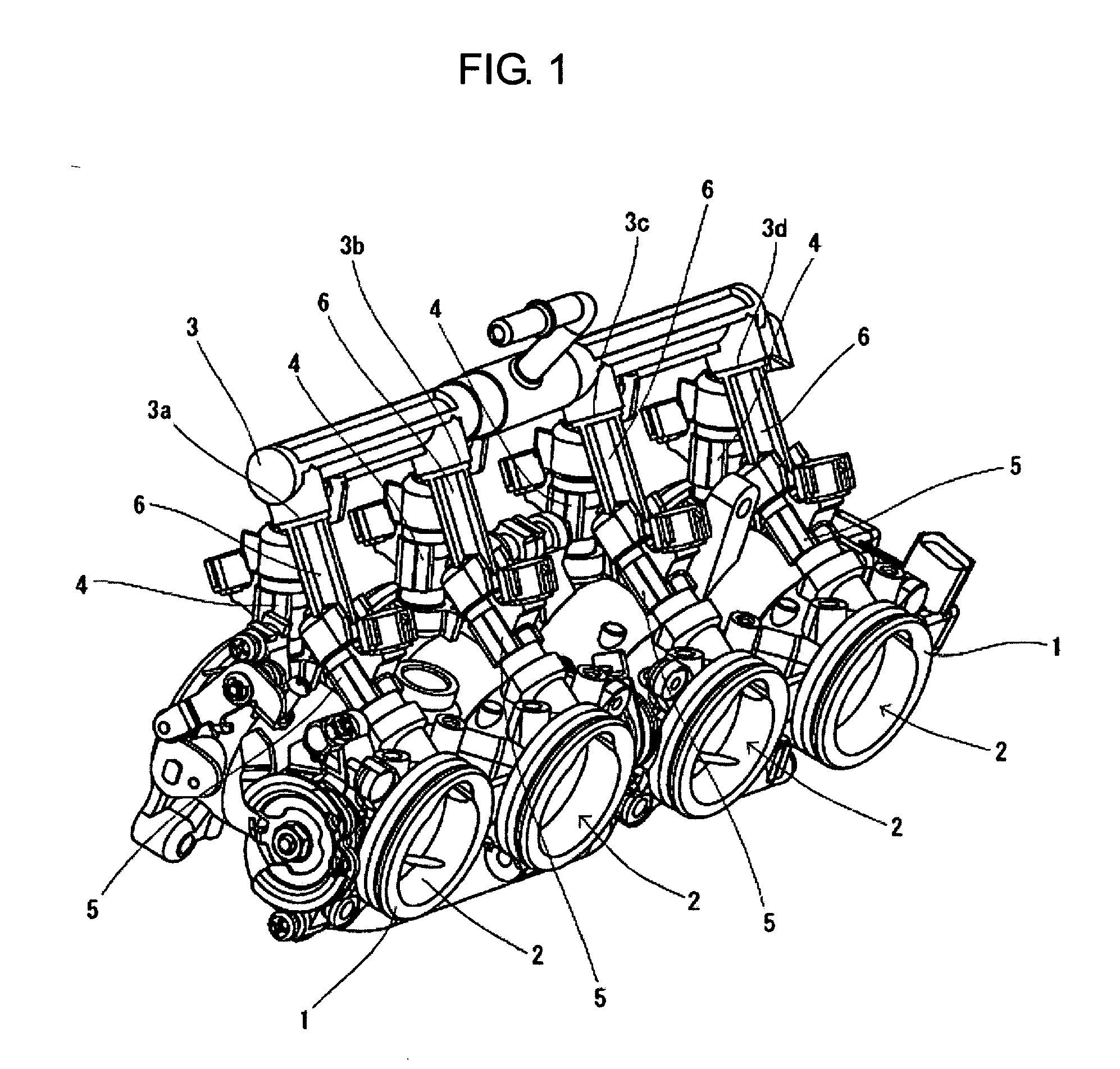
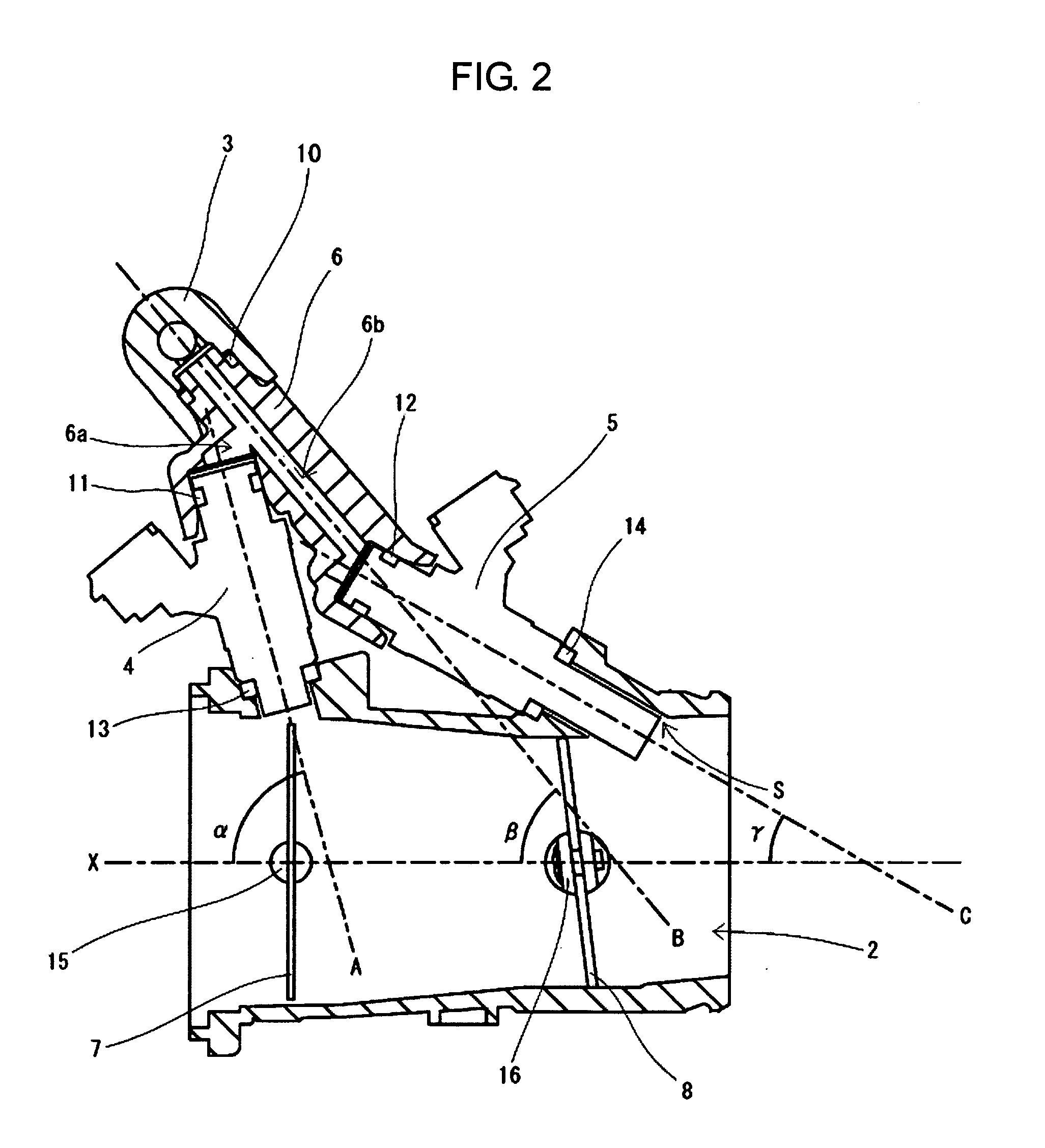
[0028]First, general structure of a fuel injection apparatus according to an embodiment of the present invention will be described with reference to FIGS. 1 to 3.

[0029]The fuel injection apparatus according to the embodiment includes throttle bodies 1 respectively incorporating an intake passage2 communicating with a combustion chamber of an engine (not illustrated), an upstream side throttle shaft 15 penetrating the throttle bodies 1 so as to be perpendicular to the respective intake passages 2, a downstream side throttle shaft 16 arranged at the downstream side of the upstream side throttle shaft 15 penetrating the throttle bodies 1 so as to be perpendicular to the respective intake passages 2 as well, upstream side throttle valves 7 fixed to the upstream side throttle shaft 15 to adjust intake ...


PUM


Abstract

A fuel injection apparatus including a plurality of throttle bodies, a fuel supply pipe to supply fuel to upstream and downstream side injectors; connecting pipes to connect the fuel supply pipe to the upstream side injectors and the downstream side injectors; upstream side branch passages to supply fuel branched from the fuel supply pipe to the respective upstream side injectors; downstream side branch passages to supply fuel branched from the fuel supply pipe to the respective downstream side injectors; a nip angle of the upstream side injectors is larger than a nip angle of the downstream side branch passages against the intake flow direction of the intake passage; and the nip angle of the downstream side branch passages is larger than a nip angle of the downstream side injectors against the intake flow direction of the intake passage.

Description

CROSS-REFERENCE TO RELATED APPLICATIONS[0001]This application claims the priority benefit of Japanese Patent Application No. 2009-257445, filed on Nov. 10, 2009, and Japanese Patent Application No. 2010-251330, filed on Nov. 9, 2010, in the Japanese Patent Office, the disclosures of which are incorporated herein by reference.BACKGROUND[0002]1. Field[0003]Embodiments relate to a fuel injection apparatus to control an air-fuel ratio in a combustion chamber of an engine, and in particular, an embodiment relates to a fuel injection apparatus to control injection fuel corresponding to an operation range with plural injectors respectively provided to each cylinder.[0004]2. Description of the Related Art[0005]In the related art, it has been known that combustion efficiency at a combustion chamber of an engine is expected to be enhanced by arranging an injection direction of an injector to direct toward the vicinity of an intake valve of the engine. In a fuel injection apparatus having two ...

Claims


Application Information

Patent Timeline
Patent Type & Authority Applications(United States)
IPC IPC(8): F02M69/46
CPCF02M69/044F02M35/10216
Inventor KIMURA, TAKAHIKOOSANAI, ATSUSHI
Owner MIKUNI CORP
Why Eureka
Try Eureka