Method and System for Heater Signature Detection Diagnostics of a Particulate Matter Sensor

a technology of particulate matter and detection diagnostics, which is applied in the direction of electrical control, instruments, nuclear elements, etc., can solve the problems of difficult to distinguish, difficult to form parts, and air pollution

Active Publication Date: 2011-05-12
DELPHI TECH IP LTD
View PDF17 Cites 39 Cited by
  • Summary
  • Abstract
  • Description
  • Claims
  • Application Information

AI Technical Summary

Problems solved by technology

Incomplete combustion of certain heavy hydrocarbon compounds, such as heavy oils, diesel fuel, and the like may lead to particulate formation (e.g., soot).
In the operation of internal combustion engines, excessive particulate formation can lead to “smoking” of the engine, which causes air pollution even though the carbon monoxide, hydrocarbons, and other pollutant components of the gaseous state exhaust emissions may be relatively low.
However, for diagnostic purposes, it can be difficult to distinguish between various states that may occur during various engine operating conditions, such as between: (i) a faulty state such as when there is an electrical open circuit in the wiring leads, which presents as a very high resistance between the sensing electrodes, and (ii) a normal state, such as when a sensor has just been cleaned, which also presents as a very high resistance, or between (i) a false positive state such as where the sensor presents a low resistance due to some cause other than soot particulates, e.g., water vapor condensate on the electrodes, and (ii) an actual positive state such as where soot particulates on the electrodes lead to a low resistance measurement.

Method used


Image

  • Method and System for Heater Signature Detection Diagnostics of a Particulate Matter Sensor
  • Method and System for Heater Signature Detection Diagnostics of a Particulate Matter Sensor
  • Method and System for Heater Signature Detection Diagnostics of a Particulate Matter Sensor

Examples


Embodiment Construction

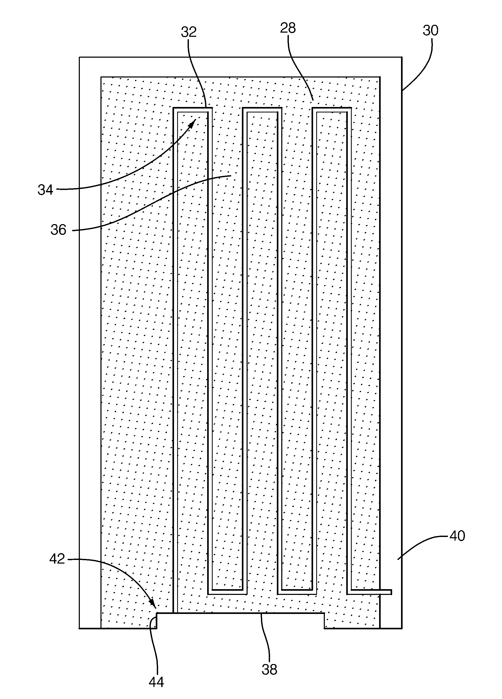
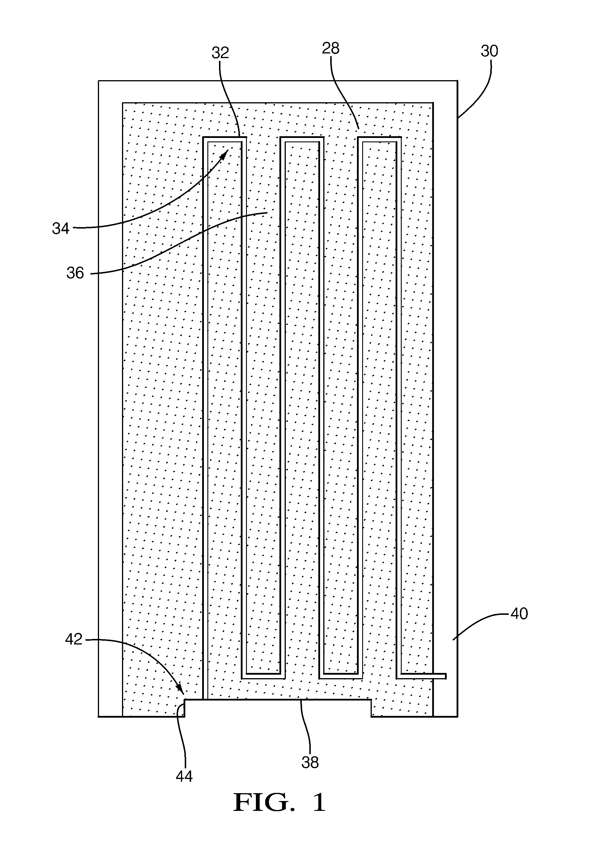
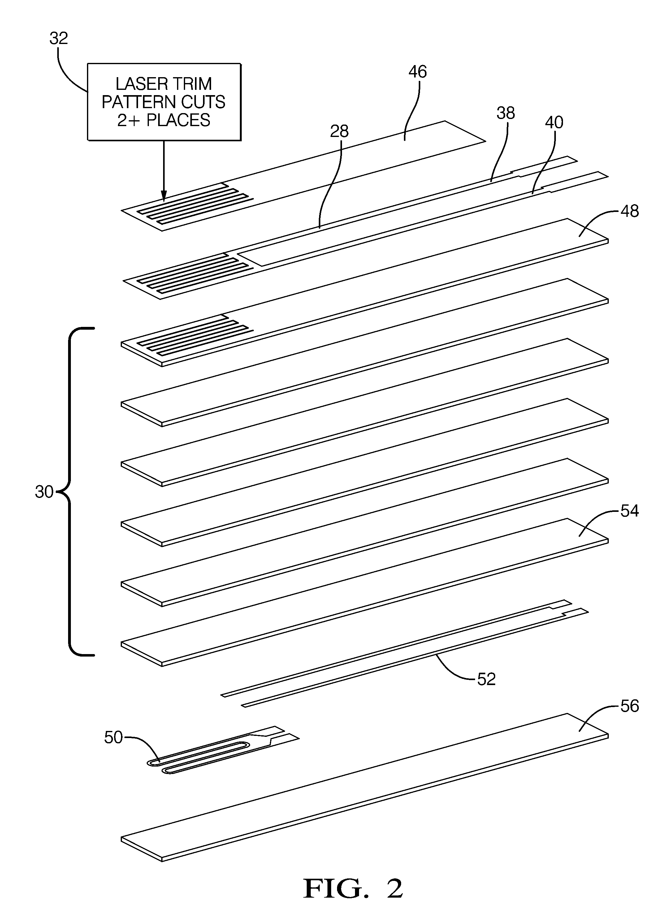
[0021]Referring now to the Figures, where the invention will be described with reference to specific embodiments, without limiting same.

[0022]In describing and claiming algorithms according to the invention, letters and naming conventions are arbitrarily employed to represent numerical values (e.g., ROBD—hot, KR—OBD—on—pct). These naming conventions are used solely to enhance the readability of the description of the invention, and are not intended to have any functional significance whatsoever. The representation of these numerical values is intended to be precisely the same as if, for example completely arbitrary descriptions (e.g., R1, R2, K1, K2) had been used. Additionally, it should be noted that in the practice of the invention, measurements of resistance between the electrodes may be made by applying a known current across the electrodes, measuring the voltage differential between the electrodes, and calculating the resistance using Ohm's law, as is well-known in the art. It...


PUM


Abstract

A diagnostic method and system is described for diagnosing an operating condition of a conductive particulate matter sensor. The sensor has a substrate with electrical resistance that varies with temperature and two electrodes on the substrate adapted to collect particulate matter between the electrodes, thereby establishing an electrically conductive path through collected particulate matter between the electrodes that can be detected by measuring electrical resistance between the electrodes, Relect. The diagnosis is performed by heating the substrate in the area between the electrodes and detecting whether resistance varies with temperature as expected, and then cooling the substrate back down and detecting whether resistance varies with temperature as expected. If resistance varies as expected during both heating and cooling, then a validation is diagnosed that the sensor is in proper operating condition if resistance increases in a manner consistent with evaporation of condensate. If resistance does not vary as expected, then a failure condition is diagnosed.

Description

BACKGROUND OF THE INVENTION[0001]This invention relates generally to sensors for detecting electrically conductive particulate matter, such as soot, and more particularly to a method and system for diagnosing potential failure modes in such sensors.[0002]Incomplete combustion of certain heavy hydrocarbon compounds, such as heavy oils, diesel fuel, and the like may lead to particulate formation (e.g., soot). In the operation of internal combustion engines, excessive particulate formation can lead to “smoking” of the engine, which causes air pollution even though the carbon monoxide, hydrocarbons, and other pollutant components of the gaseous state exhaust emissions may be relatively low. Emission regulations require many engines to limit the levels of particulate emissions, and various control technologies such as diesel particulate filters (DPF) have been employed for this purpose.[0003]In order to monitor the emission of particulate matter in the exhaust streams of certain types of...

Claims


Application Information

Patent Timeline
Patent Type & Authority Applications(United States)
IPC IPC(8): G01R27/08
CPCF02D41/029F02D41/1466G01N15/0656G01N15/0606F02D41/222
Inventor NELSON, CHARLES SCOTTHOCKEN, LARY R.
Owner DELPHI TECH IP LTD
Why Eureka
Try Eureka