Inkjet printer

a printer and inkjet technology, applied in the direction of printing, other printing apparatus, etc., can solve the problems of stains, discharge failure, and easy damage to other structural parts of the printer, and the drop of satellite ink is also easily affected

Active Publication Date: 2011-05-12
MIMAKI ENG
View PDF5 Cites 56 Cited by
  • Summary
  • Abstract
  • Description
  • Claims
  • Application Information

AI Technical Summary

Benefits of technology

[0009]According to one aspect of the present invention, an inkjet printer includes a media supporter, a head device, and an ink mist removal mechanism. The media supporter is configured to support a printing medium. The head device includes an inkjet head from which ink is configured to be discharged to print on the printing medium supported by the media supporter while the head device relatively moves with respect to the printing medium. The ink mist removal mechanism is arranged in the head device and faces the printing medium. The ink mist removal mechanism is configured to generate an air current that flows through a space between the head device and the printing medium. The ink mist removal mechanism is configured to discharge the air current to outside thereby removing ink mist generated due to ink discharge from the inkjet heads.

Problems solved by technology

Furthermore, a dropping trajectory of the satellite ink drops is also easily affected by air currents caused by movement of the head device.
The ink mist thus generated deposits on nozzle surfaces of the inkjet heads and causes discharge failure.
Furthermore, it deposits on other structural members of the printer and stains them.
Damage from such mist becomes further prominent in cases where printing is performed is a situation where there is a comparatively bigger gap between the nozzle surface (a surface on which many nozzles are formed) of the inkjet heads and the printing medium.
Moreover, the head device sucks the air while moving with respect to the printing medium.
Therefore, the air between the head device and the printing medium cannot be sucked smoothly and the ink mist cannot be removed effectively.
However, this method required special suction fans having a high suction force, or to provide plural suction fans.
Therefore, particularly, while applying to large-size inkjet printers, this method presented problems of increased cost and loud noise.

Method used


Image

  • Inkjet printer
  • Inkjet printer
  • Inkjet printer

Examples


Embodiment Construction

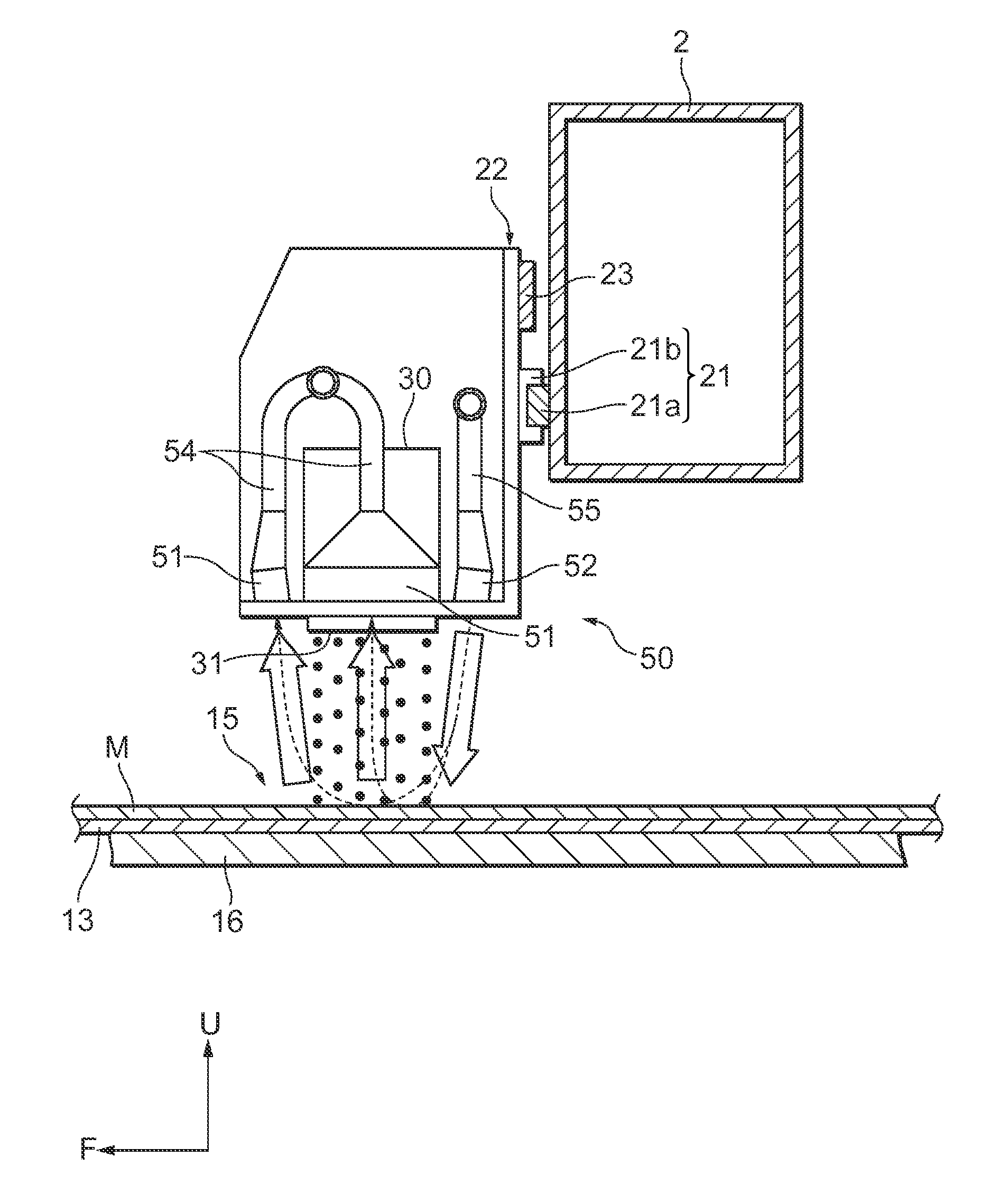
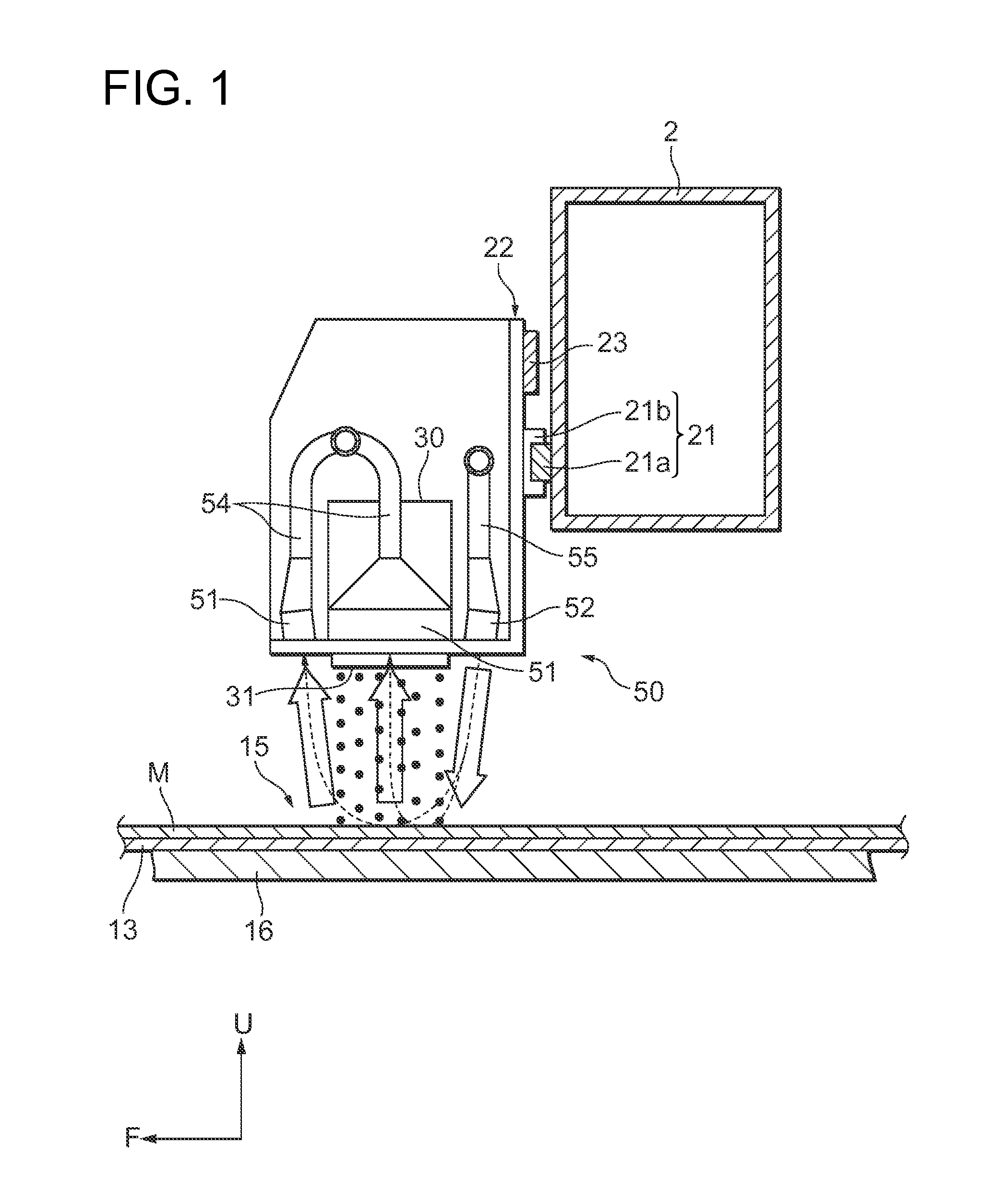
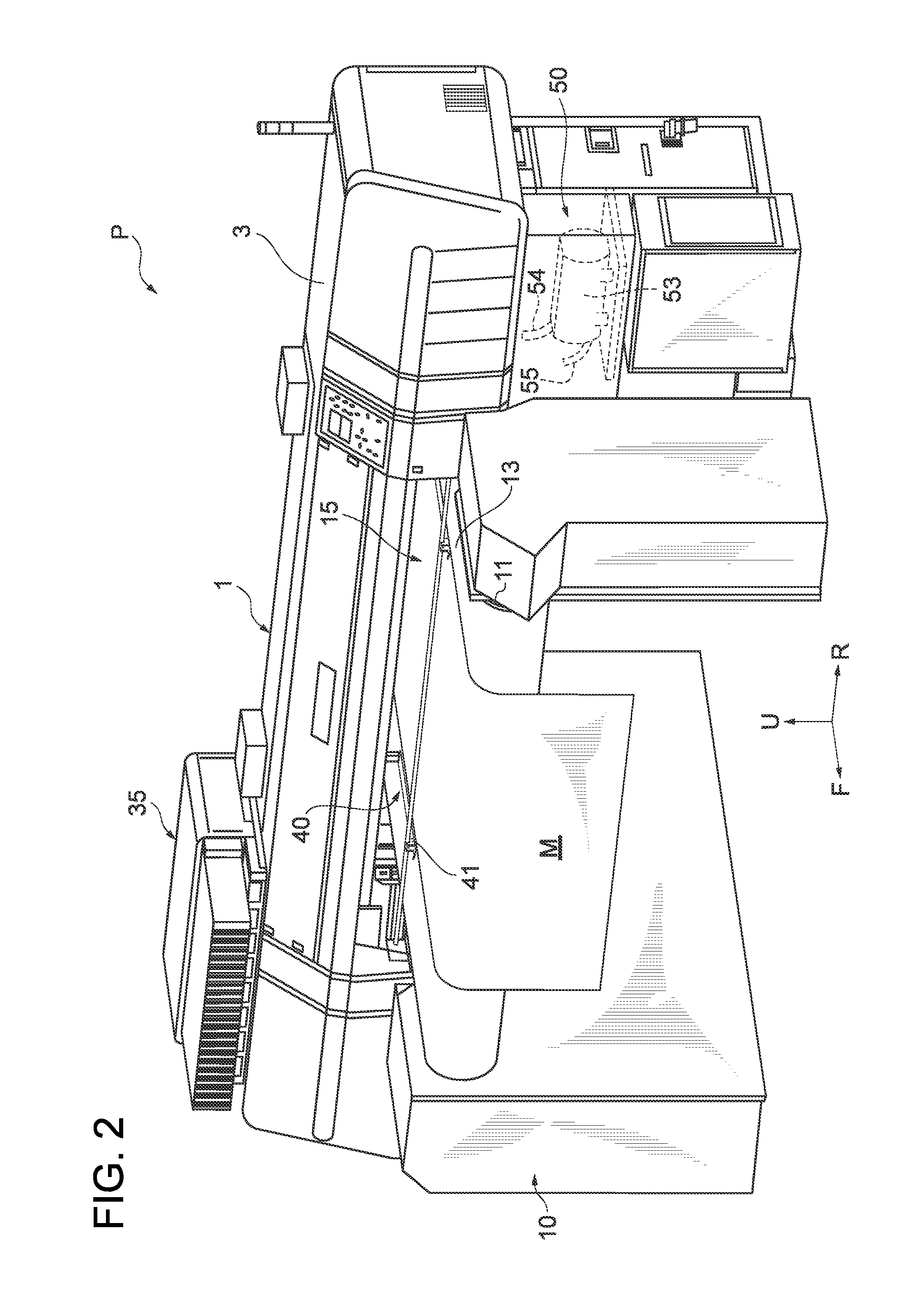
[0017]Exemplary embodiments of the present invention are explained below with reference to the accompanying drawings, wherein like reference numerals designate corresponding or identical elements throughout the various drawings. In the present embodiment, a configuration example is explained in which the embodiment of the present invention is applied to a textile inkjet printer that uses a band-shaped cloth, which is horizontally wider and longitudinally longer, as a printing medium M. FIG. 2 is a perspective view of an inkjet printer P when viewed obliquely from front and FIG. 3 is a schematic structure of the inkjet printer P. First, a schematic structure of the inkjet printer P is explained with reference to these drawings. Meanwhile, in the following explanation, directions indicated by arrows F, R, and U are forward direction, rightward direction, and upward direction, respectively.

[0018]The inkjet printer P broadly includes a media moving mechanism 10 and a head moving mechani...


PUM


Abstract

An inkjet printer includes a media supporter, a head device, and an ink mist removal mechanism. The media supporter is configured to support a printing medium. The head device includes an inkjet head from which ink is configured to be discharged to print on the printing medium supported by the media supporter while the head device relatively moves with respect to the printing medium. The ink mist removal mechanism is arranged in the head device and faces the printing medium. The ink mist removal mechanism is configured to generate an air current that flows through a space between the head device and the printing medium. The ink mist removal mechanism is configured to discharge the air current to outside thereby removing ink mist generated due to ink discharge from the inkjet heads.

Description

CROSS-REFERENCE TO RELATED APPLICATIONS[0001]The present application is a continuation application of International Application No. PCT / JP2009 / 006842, filed Dec. 14, 2009, which claims priority to Japanese Patent Application No. 2008-317918, filed Dec. 15, 2008. The contents of these applications are incorporated herein by reference in their entirety.BACKGROUND OF THE INVENTION[0002]1. Field of the Invention[0003]The present invention relates to an inkjet printer.[0004]2. Discussion of the Background[0005]In such inkjet printers, a plurality of inkjet heads corresponding to each color is arranged in a head device. Printing of desired characters or graphics, designs, photographs, etc. is performed by discharging ink drops from many nozzles provided in the inkjet heads and depositing ink layers on a printing medium. At this time, if a compatibility between the inkjet heads and the printer, or optimization of a driving method of the head device is inadequate, etc., ink drops called sat...

Claims


Application Information

Patent Timeline
Patent Type & Authority Applications(United States)
IPC IPC(8): B41J2/165
CPCB41J2/18B41J2/185B41J2/1714B41J29/17B41J29/02
Inventor OHNISHI, MASARU
Owner MIMAKI ENG
Why Eureka
Try Eureka