
System and Method of Operating a Memory Device

Active Publication Date: 2011-05-12
QUALCOMM INC
View PDF20 Cites 19 Cited by
  • Summary
  • Abstract
  • Description
  • Claims
  • Application Information

AI Technical Summary

Benefits of technology

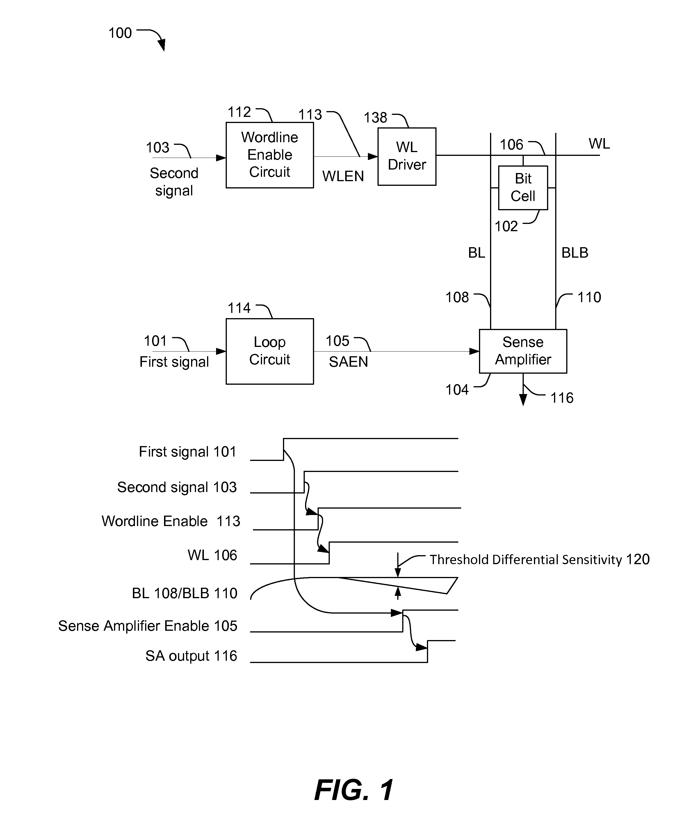
[0006]For example, by initiating operation of the loop circuit prior to initiating operation of the wordline enable circuit, significant delays due to reduced logic supply voltage can be compensated for at the loop circuit to maintain a substantially constant delay between a wordline bias and a sense amplifier enable signal. As a result, an amount of differential voltage development during a memory read may be substantially unaffected by lowering the logic supply voltage, enabling increased power savings.
[0009]One particular advantage provided by at least one of the disclosed embodiments is that, because the loop circuit receives the first signal before the wordline enable signal receives the second signal, a delay of the loop circuit in generating a sense amplifier enable signal due to a reduced supply voltage can be accommodated even when the delay exceeds the time required for a threshold differential voltage to be developed after the second signal is received at the wordline enable circuit. As a result, lower power operation may be achieved than in systems where the loop circuit and the wordline enable circuit are triggered by a common signal.

Problems solved by technology

Reducing a supply voltage of electronic elements typically results in lower power consumption.
However, some electronic elements may operate at a slower speed with a reduced supply voltage.
Such slower speed may impact operation of certain circuits within the electronic device.

Method used


Image

  • System and Method of Operating a Memory Device
  • System and Method of Operating a Memory Device
  • System and Method of Operating a Memory Device

Examples


first embodiment

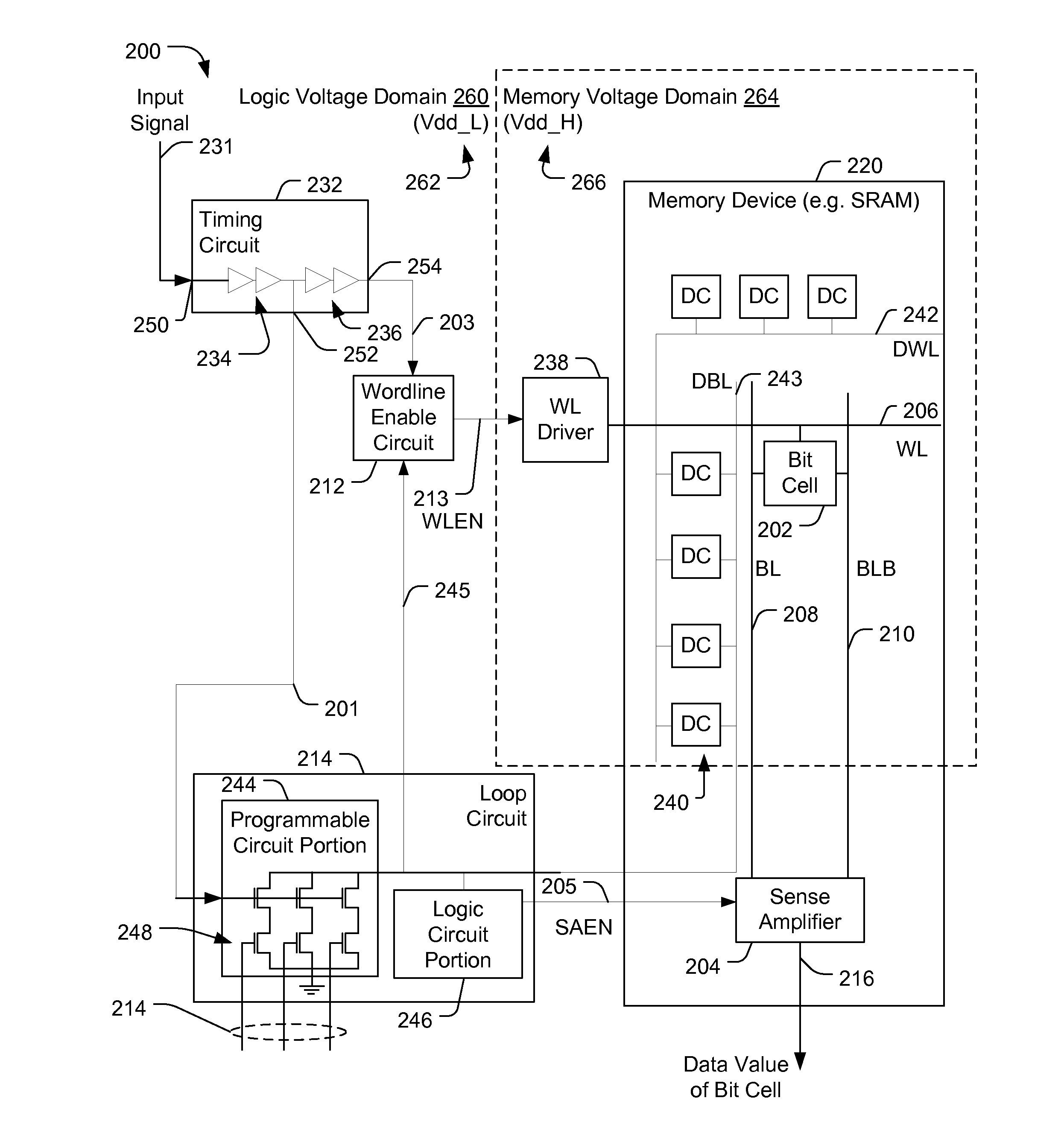
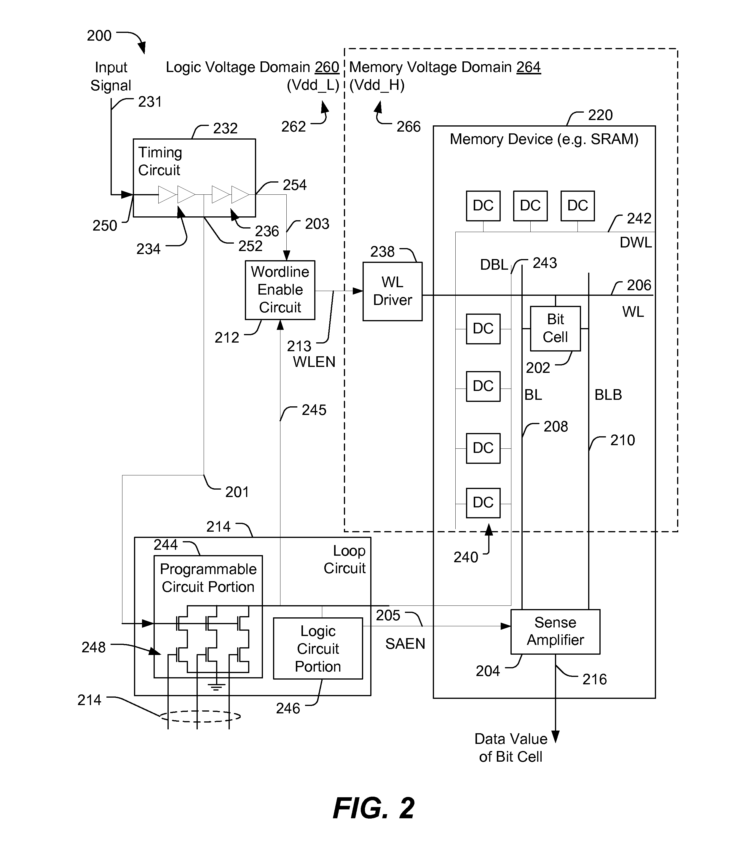
[0047]Referring to FIG. 5, a method of operating a memory system is depicted. In an illustrative embodiment, the method may be performed at the system of FIG. 1 or FIG. 2. The method includes receiving an input signal at a memory device that includes a bit cell that is coupled to a wordline and that is coupled to a sense amplifier via a first bit line and a second bit line, at 502. For example, the input signal 231 of FIG. 2 is received at the timing circuit 232 of the memory system 200 that also includes the bit cell 202 coupled to the sense amplifier 204 via bit lines 208 and 210.

[0048]The method includes, in response to receiving the input signal, sending a first signal to a loop circuit to initiate an operation of the loop circuit, at 504, and sending a second signal to a wordline enable circuit to initiate generation of a wordline signal at the wordline, at 506. The first signal is sent before the second signal. For example, the first signal 201 of FIG. 2 is provided to the loo...

second embodiment

[0051]Referring to FIG. 6, a method of operating a memory system is depicted. In an illustrative embodiment, the method may be performed at the system of FIG. 1 or FIG. 2.

[0052]The method may include programming a loop circuit based on a supply voltage of a logic domain to maintain a substantially constant delay between a wordline signal and a sense amplifier enable signal, at 602. The substantially constant delay is substantially independent of a logic domain voltage. For example, the loop circuit 214 of FIG. 2 may be programmed based on the supply voltage Vdd_L 262 to maintain the substantially constant delay 322 of FIG. 3.

[0053]In a particular embodiment, a control signal is provided to multiple discharge devices of the programmable circuit portion to control a rate of discharge of a precharged dummy bit line, at 604. For example, the control signal may be the control signal 214 of FIG. 2 provided to the multiple discharge devices 248 to control a rate of discharge of the prechar...


PUM


Abstract

A system and method of operating a memory device is disclosed. In a particular embodiment, an apparatus is disclosed that includes a bit cell coupled to a first bit line and to a second bit line. The apparatus also includes a sense amplifier coupled to the first bit line and to the second bit line. The apparatus includes a loop circuit configured to provide a sense amplifier enable signal to the sense amplifier in response to receiving a first signal. The apparatus also includes a wordline enable circuit configured to provide a wordline enable signal to a wordline driver in response to receiving a second signal. The loop circuit receives the first signal before the wordline enable circuit receives the second signal.

Description

I. FIELD[0001]The present disclosure is generally related to operating a memory device.II. DESCRIPTION OF RELATED ART[0002]Advances in technology have resulted in smaller and more powerful computing devices. For example, there currently exist a variety of portable personal computing devices, including wireless computing devices, such as portable wireless telephones, personal digital assistants (PDAs), and paging devices that are small, lightweight, and easily carried by users. More specifically, portable wireless telephones, such as cellular telephones and Internet protocol (IP) telephones, can communicate voice and data packets over wireless networks. Further, many such wireless telephones include other types of devices that are incorporated therein. For example, a wireless telephone can also include a digital still camera, a digital video camera, a digital recorder, and an audio file player. Also, such wireless telephones can process executable instructions, including software app...

Claims


Application Information

Patent Timeline
IPC IPC(8): G11C7/00G11C8/08G11C7/02
CPCG11C7/08G11C7/14G11C7/22G11C7/222G11C2207/065G11C8/08G11C11/418G11C11/419G11C7/227G11C7/10G11C7/06
Inventor CHO, SUNG ILYOON, SEI SEUNGGUNDUBOGULA, NAVEENABU-RAHMA, MOHAMED H.PARK, DONGKYU
Owner QUALCOMM INC
Learn More