Continuous compressor envelope protection

a compressor and envelope protection technology, applied in the direction of machines/engines, positive displacement liquid engines, lighting and heating apparatus, etc., can solve the problems of relatively low discharge pressure and temperature, and the compressor will be driven at a relatively slow speed

Inactive Publication Date: 2011-05-12
CARRIER CORP
View PDF24 Cites 33 Cited by
  • Summary
  • Abstract
  • Description
  • Claims
  • Application Information

AI Technical Summary

Problems solved by technology

However, when the engine is idling, for example, then the compressor will be driven at a relatively slow speed, and the discharge pressure and temperature will be relatively low.

Method used


Image

  • Continuous compressor envelope protection
  • Continuous compressor envelope protection
  • Continuous compressor envelope protection

Examples


Embodiment Construction

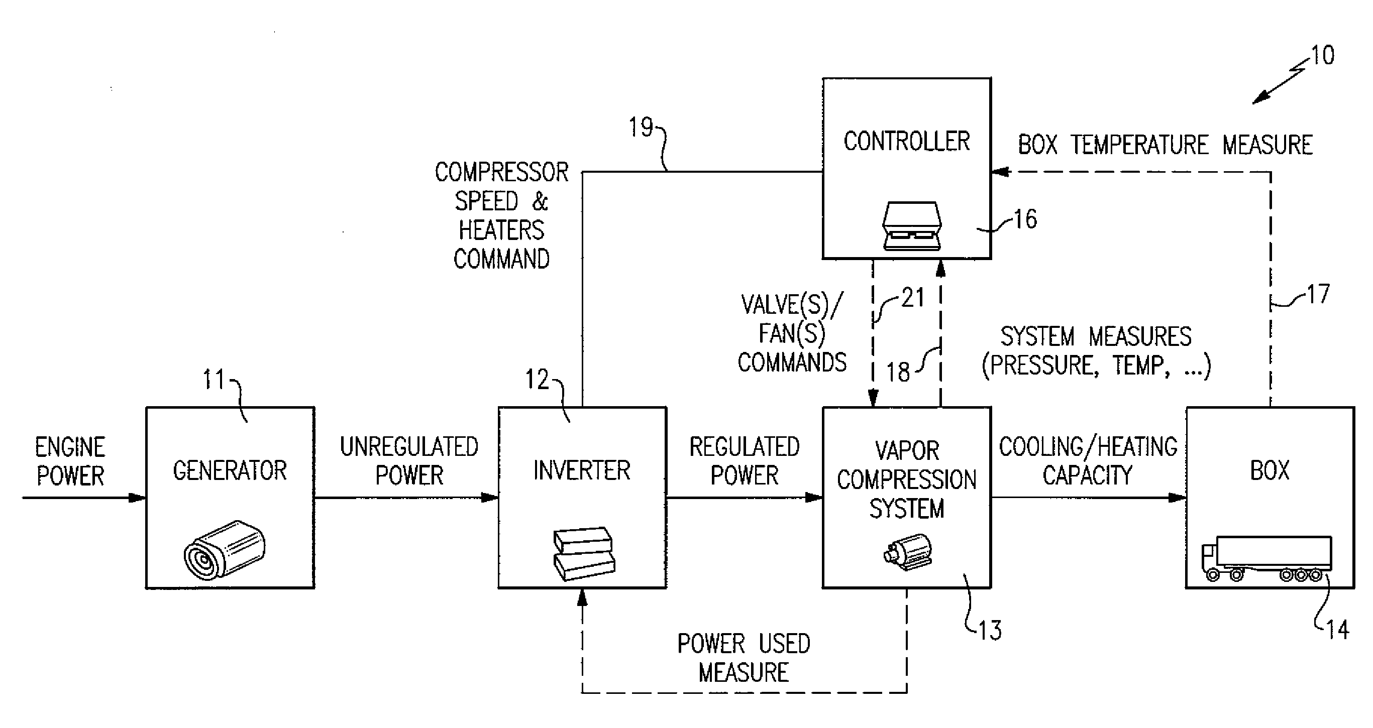
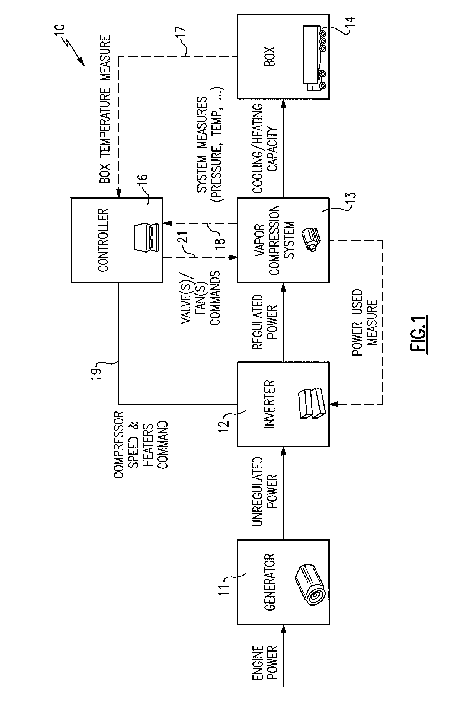
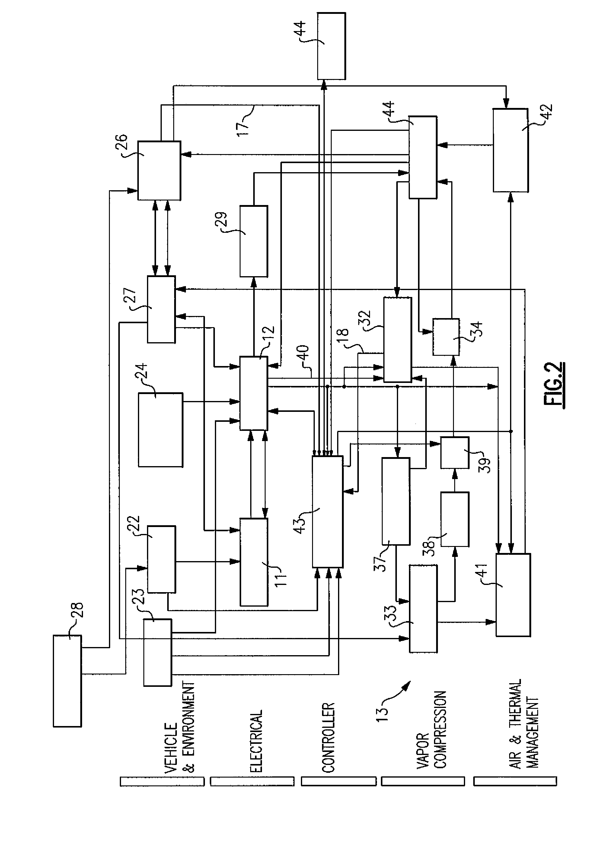
[0010]The invention is shown generally at 10 in FIG. 1 to include a generator 11, which is driven by the power of the vehicle engine, an inverter 12, which receives unregulated voltage from the generator 11, a vapor compression system 13, which receives regulated power regulated (i.e voltage and frequency) from the inverter 12, a box 14 which receives cooled air from the vapor compression system 13, and a controller 16, which receives box temperature measurements (i.e. return air temperatures, RAT) from the box 14 along line 17, and pressure and temperature measurements from the vapor compression system 13 along lines 18 in order to control the inverter 12 by way of line 19. The controller 16 also sends cooling demand signals to the vapor compression system 13 by way of line 21. A more detailed illustration of the system is shown in FIG. 2.

[0011]Considering first the vehicle itself and the environment surrounding that vehicle, there is included a drive engine 22, a battery 23, a sta...


PUM


Abstract

A transport refrigeration system is provided with a control apparatus including an inverter and a microprocessor, with the microprocessor receiving signals representative of sensed values of the compressor discharge temperature and pressure, as well as the suction pressure, and controlling the inverter to responsively provide a selective level of electrical voltage and frequency to the compressor in order to maintain a desired compressor envelope.

Description

TECHNICAL FIELD[0001]This invention relates generally to transport refrigeration systems and, more particularly, to control of a compressor motor drive in a vapor compression system therefor.BACKGROUND OF THE INVENTION[0002]Transport refrigeration systems are commonly used in refrigerated trucks, truck trailers and containers in order to preserve perishable cargo during transport from one location to another. Such a system includes the necessary components for a vapor compression cycle, including a compressor which necessarily includes some type of drive means. For containers and truck trailers, this function has generally been provided by a dedicated internal combustion engine with its speed being selectively varied in order to maintain a desired compressor envelope. In refrigerated trucks and vans, however, the compressor has generally been located within the main engine drive compartment, with the compressor then being driven by direct connection to the main engine drive. Conduit...

Claims


Application Information

Patent Timeline
Patent Type & Authority Applications(United States)
IPC IPC(8): F04B49/00
CPCB60H1/3232B60H2001/325B60H2001/3257B60H2001/3292F25B2700/21171F25B2600/021F25B2700/1931F25B2700/1933F25B2700/21152F25B49/022
Inventor DONNAT, GILLESVARIGONDA, SUBBARAOMIJANOVIC, STEVO
Owner CARRIER CORP
Why Eureka
Try Eureka