Flexible medical ablation device and method of use

a medical ablation and flexible technology, applied in the field of flexible medical ablation devices and methods of use, can solve the problems of inability to effectively use tissue treatment systems in conjunction with imaging devices, inability to hold shape, and inability to allow effective positioning of energy delivery components within the patien

Inactive Publication Date: 2011-05-12
ANGIODYNAMICS INC
View PDF35 Cites 43 Cited by
  • Summary
  • Abstract
  • Description
  • Claims
  • Application Information

AI Technical Summary

Benefits of technology

[0012]The present invention provides among other things the capability to bend and conform a section of a device for tissue treatment so that the probe can be placed at a designated location with the distal portion (including the tip) placed within a patient while more proximal portions external to the patient can conform to the patient's shape as necessary (can match the conformation of the patient), and both the patient and probe can be positioned within a machine capable of visualizing at least a portion of the patient as well as the probe without the need for removal of the probe. These capabilities allow for use of the probe with additional medical devices. In one exemplary embodiment, the flexible section can be configured to be capable of bending so as to match the conformation (surface profile) of said patient from a point starting at the distal end of said handle of said probe to a point at the proximal end of said rigid needle section.

Problems solved by technology

In many cases the tissue treatment system cannot be used effectively in conjunction with the imaging device; for example when a patient is of a large body mass index, multiple problems exist that are not solved by current technology; the distance between the patient and the imaging tube may be minimal so tissue treatment system energy delivery components cannot be placed into the patient and left there while the patient is in the imaging device because of spatial limitations.
A system that is solely rigid will not be compatible with varying shapes of patients and sizes of visualization systems; at the same time a system that cannot hold shape will be unable to allow effective positioning of the energy delivery component within the patient.

Method used


Image

  • Flexible medical ablation device and method of use
  • Flexible medical ablation device and method of use
  • Flexible medical ablation device and method of use

Examples


Embodiment Construction

[0041]In the following description, and for the purposes of explanation, numerous specific details are set forth in order to provide a thorough understanding of the various aspects of the invention. It will be understood, however, by those skilled in the relevant arts, that the present invention can be practiced without these specific details. In other instances, known structures and devices are shown or discussed more generally in order to avoid obscuring the invention. In many cases, a description of the operation is sufficient to enable one to implement the various forms of the invention. It should be noted that there are many different and alternative configurations, devices and technologies to which the disclosed inventions can be applied. The full scope of the inventions is not limited to the examples that are described below.

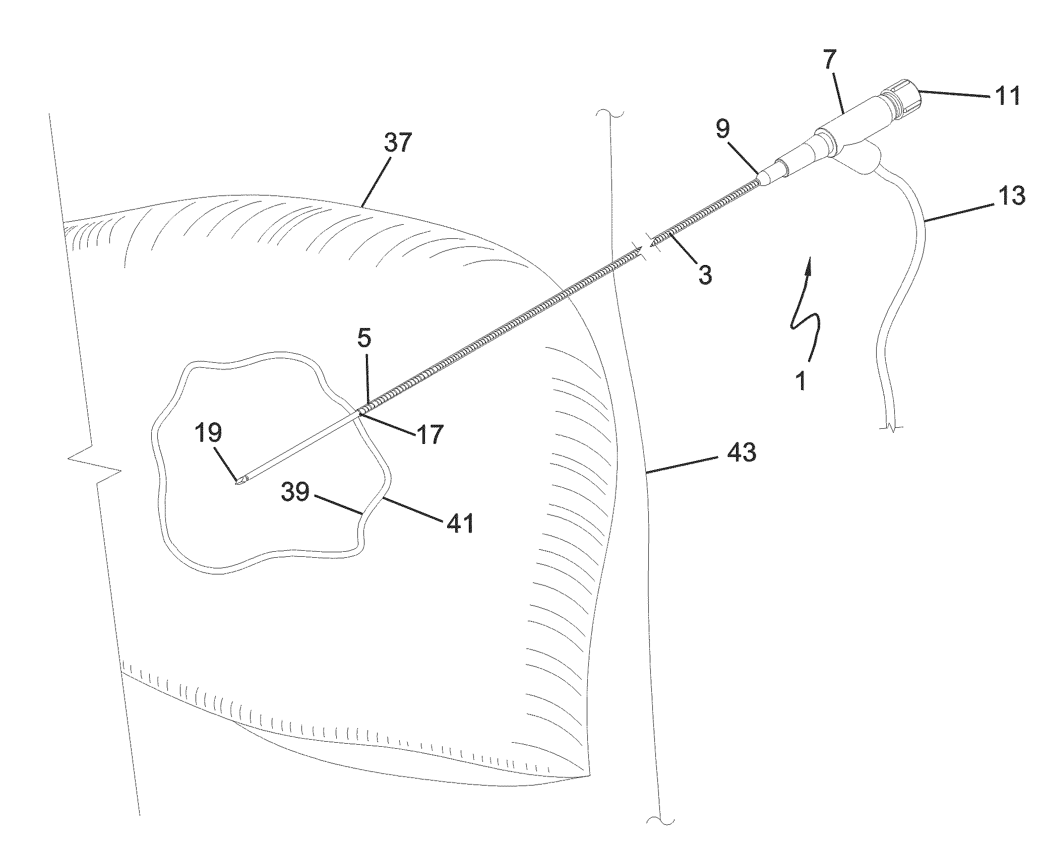
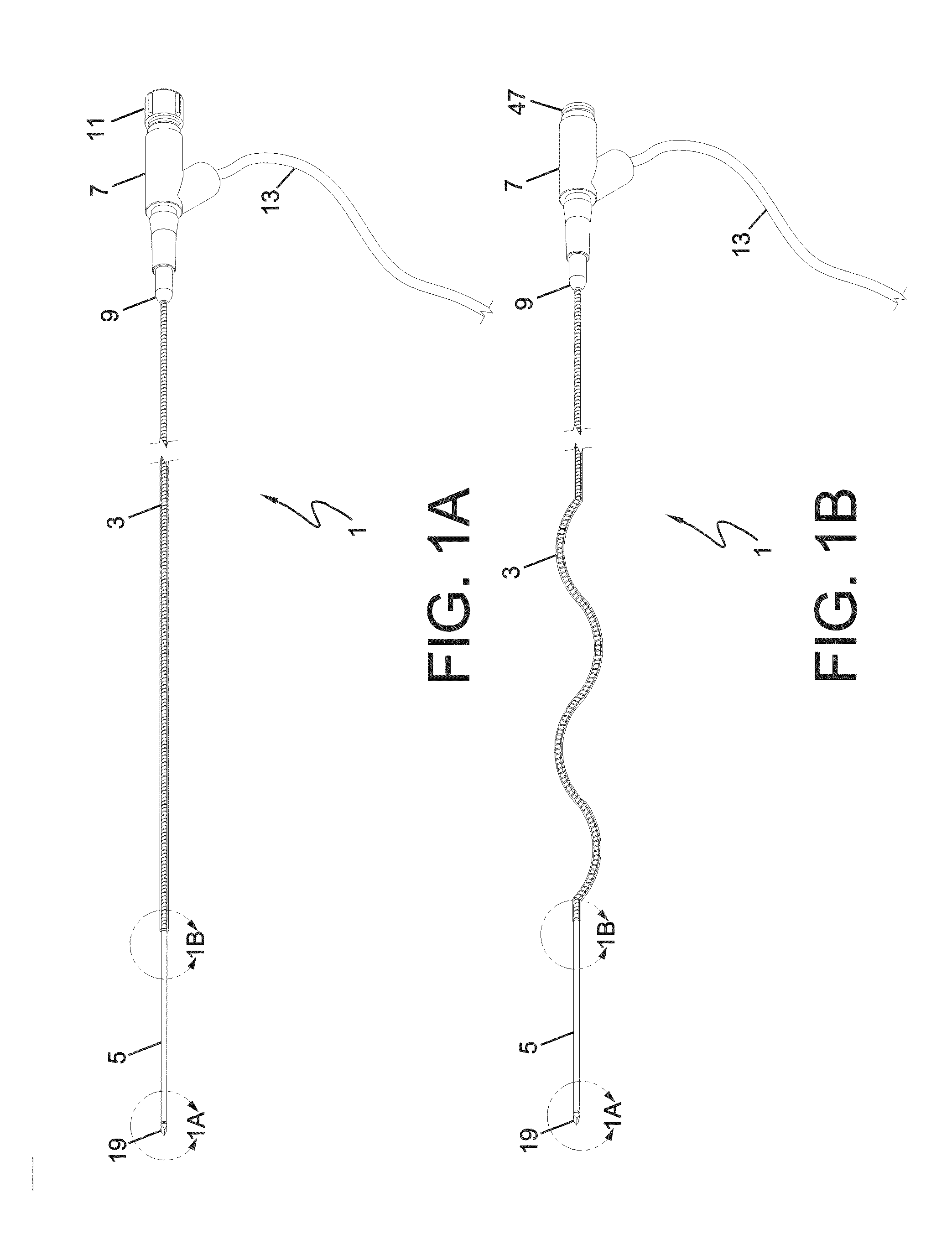
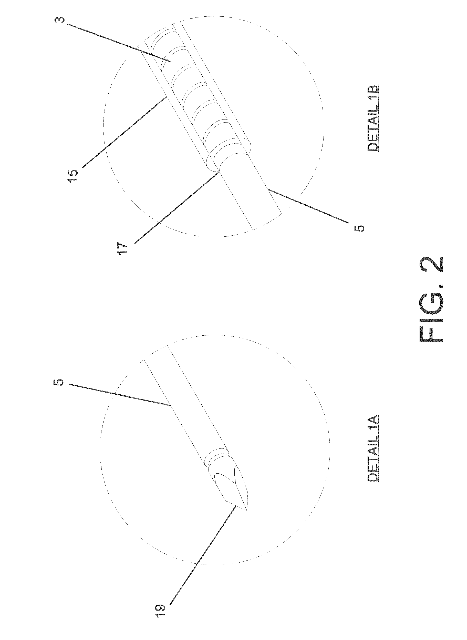
[0042]FIGS. 1A and 1B are plan views of a device designed for tissue treatment having a flexible needle section 3, a rigid needle section 5, and a tissue...


PUM


Abstract

Disclosed herein are methods and devices involving a medical probe placeable into tissue where the probe has a high pushability yet is capable of being conformed to a patient's shape due to use of a removable stiffener and a flexible needle section allowing for placement, imaging, and treatment to be performed without removal of the probe regardless of environmental and physical restrictions related to devices used during the patient's procedure.

Description

BACKGROUND OF THE INVENTION[0001]1. Field of the Invention[0002]The present invention relates generally to methods and devices involving a medical device with a flexible needle section where the device is capable of providing tissue treatment. More specifically, the invention relates to devices and methods regarding a device designed to be capable of significant pushability for placement as well as significant flexibility allowing for the device profile to be altered so as to allow maximum compatibility for use with medical devices and procedures including imaging.[0003]2. Description of the Related Art[0004]Comprehensive medical care involves utilization of a significant number of simultaneously coordinated technologies that must be compatible to be effective. For example technology for tissue treatment (including tissue ablation) must be used in conjunction with advanced visualization systems. For example, imaging technologies or imaging devices can be used to determine the positi...

Claims


Application Information

Patent Timeline
Patent Type & Authority Applications(United States)
IPC IPC(8): A61B18/14
CPCA61B17/22012A61B17/3468A61B17/3478A61B18/082A61B18/1477A61B18/1492A61B2018/1425A61B18/1815A61B18/20A61B19/5225A61B2017/3405A61B2018/044A61B2018/1266A61B18/18A61B90/37
Inventor HAMILTON, JR., WILLIAM C.DI PALMA, GIORGIO
Owner ANGIODYNAMICS INC
Why Eureka
Try Eureka