Device for the aftertreatment of exhaust gases of internal combustion engines

a technology for exhaust gases and internal combustion engines, which is applied in the direction of exhaust treatment, engine components, mechanical equipment, etc., can solve the problems of insufficient solution, inability to prevent the formation of cyanuric acid, melamine, or other unwanted solid reaction products, and the difficulty of distributing the reductant in the correct quantities, etc., to achieve small installation space, simple

Active Publication Date: 2011-05-19
MAN NUTZFAHRZEUGE AG
View PDF2 Cites 85 Cited by
  • Summary
  • Abstract
  • Description
  • Claims
  • Application Information

AI Technical Summary

Benefits of technology

[0014]An object of one embodiment of the invention is a device for the aftertreatment of exhaust gases in an exhaust gas system in internal combustion engines, particularly in lean-burn internal combustion engines, of motor vehicles, e.g., uti

Problems solved by technology

In internal combustion engines operated in motor vehicles, nitrogen oxide reduction by the SCR method is difficult because of changing operating conditions, which makes it more difficult to apportion the reductant in the correct quantities.
However, when the exhaust gas temperatures are too low, this method does not fully solve the problem of incomplete hydrolysis of urea.
In spite of all of these steps, it is often not possible to prevent the formation of cyanuric acid, melamine, or other unwanted solid reaction products, particularly when the NH3 precursor substance, such as urea or aqueous urea solution, and the exhaust gas a

Method used


Image

  • Device for the aftertreatment of exhaust gases of internal combustion engines
  • Device for the aftertreatment of exhaust gases of internal combustion engines
  • Device for the aftertreatment of exhaust gases of internal combustion engines

Examples


Embodiment Construction

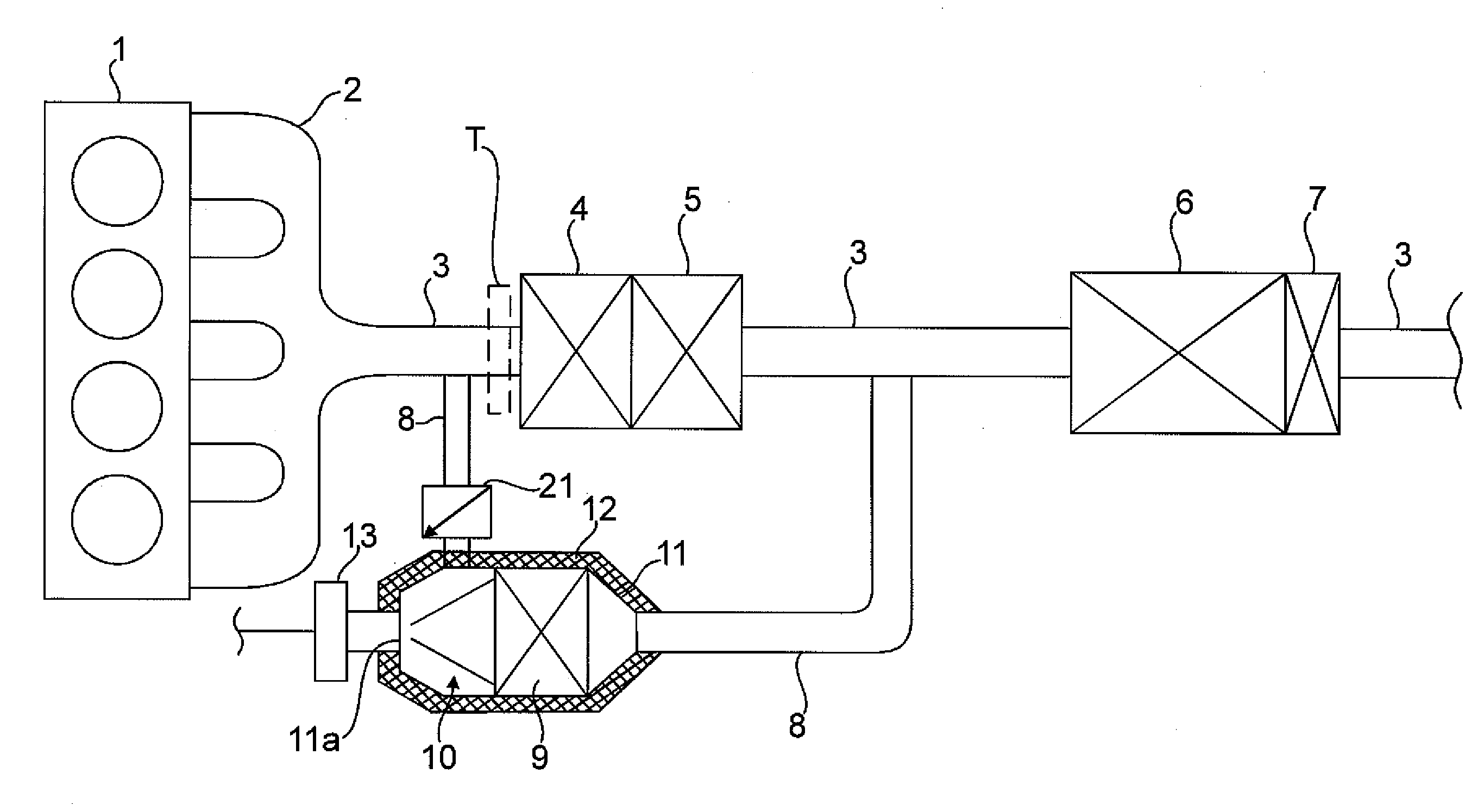
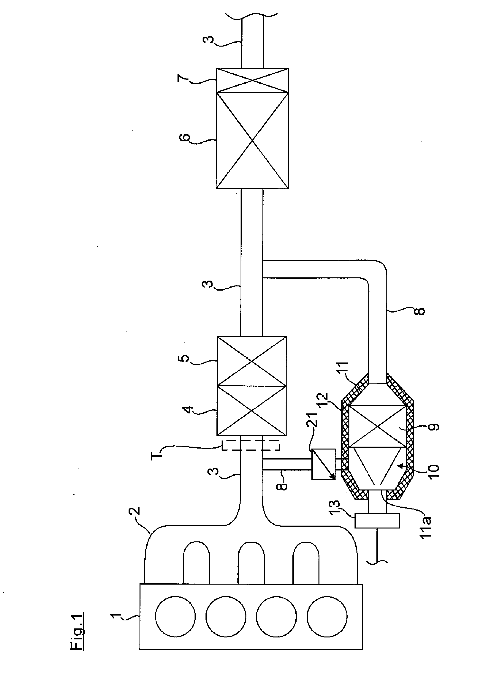
[0050]In FIG. 1, an internal combustion engine which is merely suggested in the drawing is designated by reference numeral 1. Its exhaust gases are guided out of the combustion chambers, of which there are four in this instance, via an exhaust gas manifold 2 to an exhaust gas line 3.

[0051]Considered in the direction of the exhaust gas flow, an oxidation catalyst 4, a particulate filter 5 and, finally, a SCR catalyst 6 with a NH3 slip catalyst 7 are arranged in the exhaust gas line 3. These exhaust gas aftertreatment devices 4, 5, 6 and 7 are of conventional construction are not described.

[0052]Upstream of the oxidation catalyst 4, a branch line 8 is connected to the exhaust gas line 3 and is fed back into the exhaust gas line 3 again downstream of the particulate filter 5 and upstream of the SCR catalyst 6.

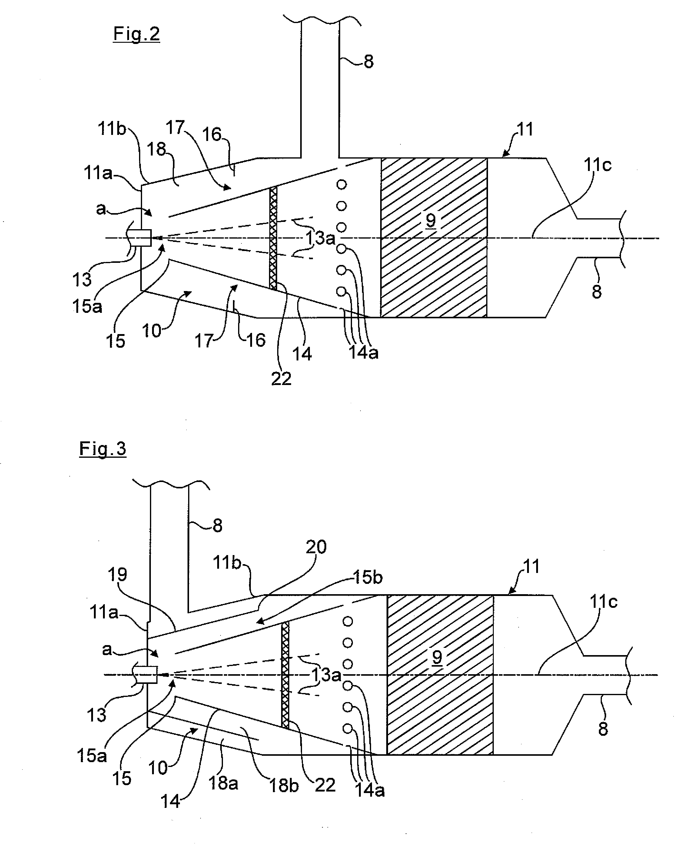
[0053]A hydrolysis catalyst 9 with an inlet section 10 in front of it is provided in the branch line 8. The inlet section 10 is arranged in a common, approximately cylindrical hou...


PUM


Abstract

A device for the aftertreatment of exhaust gases in an exhaust gas system of internal combustion engines, having at least one reductant decomposition catalyst. Arranged in the exhaust gas flow, and a metering device arranged upstream of the latter in an exhaust gas line for supplying reductant. Preferably at least one other catalyst device is provided downstream of the reductant decomposition catalyst. An inlet section for the exhaust gas having at least one flow deflection area is arranged upstream of the reductant decomposition catalyst and constructed for the exhaust gas to be fed into a housing radially outside an inlet pipe adjoining the reductant decomposition catalyst that encloses the inlet pipe, and is guided in counterflow through a front inlet opening of the inlet pipe to the reductant decomposition catalyst. The reductant is fed into the flow deflection area associated with the inlet opening.

Description

BACKGROUND OF THE INVENTION[0001]1. Field of the Invention[0002]The invention is directed to a device for the aftertreatment of exhaust gases of internal combustion engines, particularly of lean-burn internal combustion engines in motor vehicles[0003]2. Description of the Related Art[0004]The use of selective catalytic reduction (SCR) catalysts to reduce nitrogen oxides in a stream of exhaust gas in an internal combustion engine is well known. For purposes of the SCR carried out by these SCR catalysts, a substance having a directly reductive action, e.g., ammonia or a precursor, which first releases reductive substances in the exhaust gas is fed to the stream of exhaust gas. An aqueous urea solution, for example, can be used as a precursor.[0005]In internal combustion engines operated in motor vehicles, nitrogen oxide reduction by the SCR method is difficult because of changing operating conditions, which makes it more difficult to apportion the reductant in the correct quantities. ...

Claims


Application Information

Patent Timeline
IPC IPC(8): F01N3/18
CPCF01N3/2066F01N3/2892F01N2240/20F01N2240/40Y02T10/24F01N2490/06F01N2610/02F01N2610/1453F01N2470/18Y02A50/20Y02T10/12
Inventor TILINSKI, MARCOKLINGSPORN, ANDREASDORING, ANDREASKISTNER, ANDREASSEIDEL, PETRA
Owner MAN NUTZFAHRZEUGE AG
Why Eureka
Try Eureka