Pilot combustor in a burner

a burner and combustor technology, applied in the field of burners, can solve the problems of unsteady fluid dynamic process, thermo-acoustic instabilities, and movement of flames, and achieve the effect of rapid and stable combustion

Inactive Publication Date: 2011-05-19
SIEMENS AG
View PDF17 Cites 27 Cited by
  • Summary
  • Abstract
  • Description
  • Claims
  • Application Information

AI Technical Summary

Benefits of technology

[0015]Disclosed is a pilot combustor for use in a lean-rich partially premixed low emissions burner for a gas turbine combustor that provides stable ignition and combustion process at all engine load conditions. This burner operates according to the principle of “supplying” heat and high concentration of free radicals from the a pilot combustor exhaust to a main flame burning in a lean premixed air/fuel swirl, whereby a rapid and stable combustion of the main lean premixed flame is supported. The pilot combus

Problems solved by technology

The major problems associated with the combustion process in gas turbine engines, in addition to thermal efficiency and proper mixing of the fuel and the air, are associated to flame stabilization, the elimination of pulsations and noise, and the control of polluting emissions, especially nitrogen oxides (NOx), CO, UHC, smoke and particulated emission.
A less stable, easy to move flame front of a pre-mixed flame results in a periodic heat release rate, that, in turn, results in

Method used


Image

  • Pilot combustor in a burner
  • Pilot combustor in a burner
  • Pilot combustor in a burner

Examples


Embodiment Construction

[0045]In the following a number of embodiments will be described in more detail with references to the enclosed drawings.

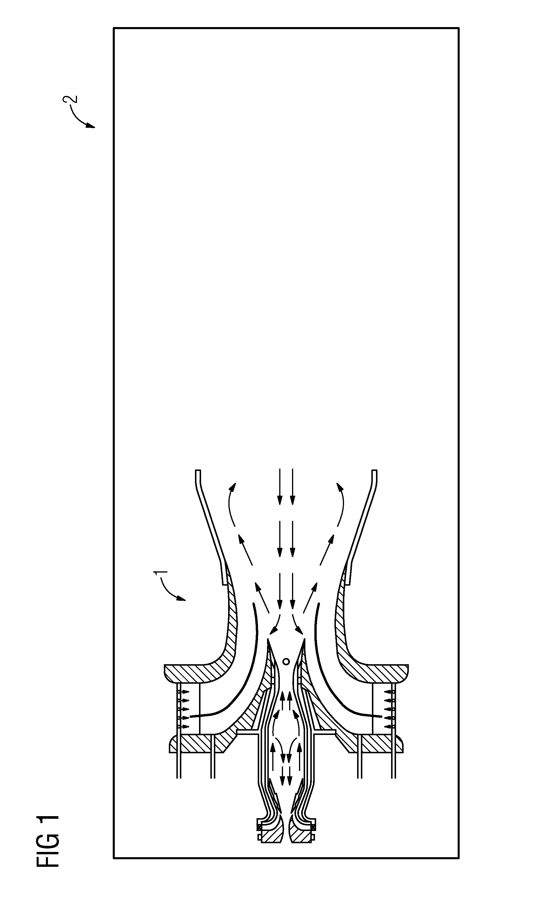
[0046]In FIG. 1 a burner 1 provided with the pilot combustor according to the aspect of the present invention is depicted with the burner 1 having a housing 2 enclosing the burner components.

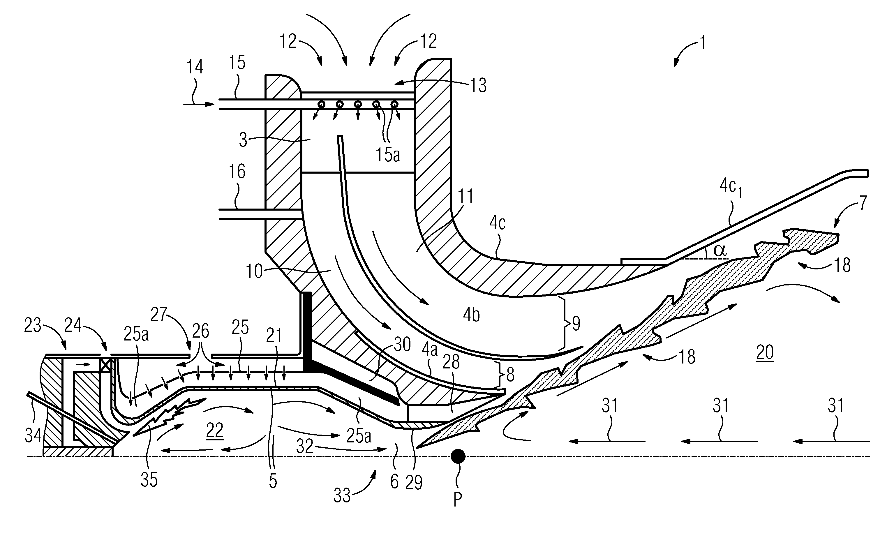
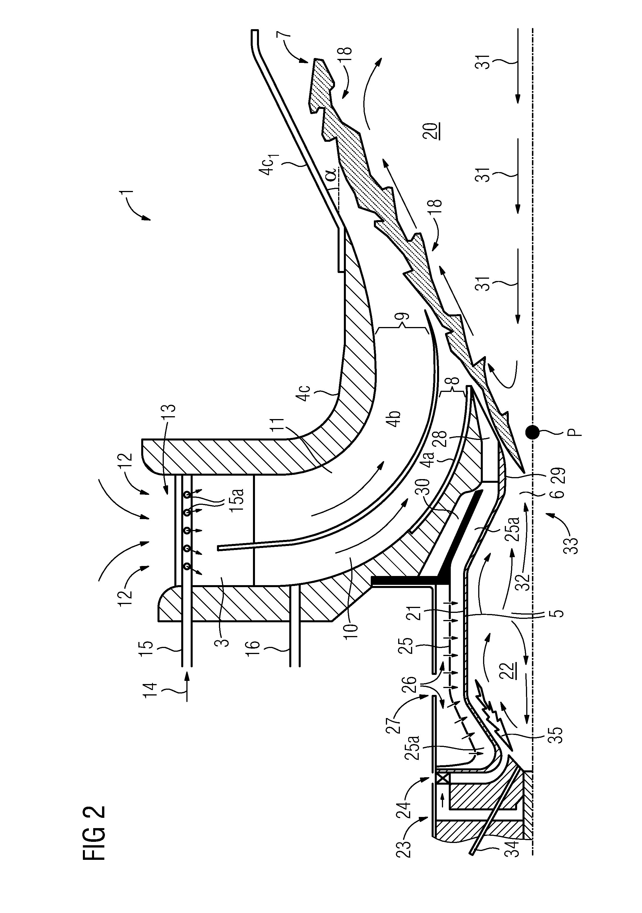
[0047]FIG. 2 shows for the sake of clarity a cross sectional view of the burner 1 above a rotational symmetry axis. The main parts of the burner 1 are the radial swirler 3, the multi quarl 4a, 4b, 4c and the pilot combustor 5.

[0048]As stated, the burner 1 operates according to the principle of “supplying” heat and high concentration of free radicals from the a pilot combustor 5 exhaust 6 to a main flame 7 burning in a lean premixed air / fuel swirl emerging from a first exit 8 of a first lean premixing channel 10 and from a second exit 9 of a second lean premixing channel 11, whereby a rapid and stable combustion of the main lean premixed flame 7 is supported. Said first lean pr...


PUM


Abstract

A pilot combustor particularly for use in a burner of a gas turbine engine is provided. A method for burning a fuel in a pilot combustor zone of a pilot combustor is also provided. The pilot combustor includes rotationally symmetric walls defining a combustion room with an exit having a rich concentration of fuel in air for burning the fuel for the creation of a flow of an non equilibrium unquenched concentration of radicals elevated to a temperature above 2000 K in the combustion room and directed along a centre line of the pilot combustor through a throat at the exit of the pilot combustor, wherein a quarl is located downstream of the throat of the pilot combustor. According to the method the pilot combustor is arranged upstream of a burner for providing a main lean partially premixed combustion process.

Description

CROSS REFERENCE TO RELATED APPLICATIONS[0001]This application is the US National Stage of International Application No. PCT / EP2009 / 053565, filed Mar. 26, 2009 and claims the benefit thereof. The International Application claims the benefits of European Patent Office application No. 08006660.8 EP filed Apr. 1, 2008. All of the applications are incorporated by reference herein in their entirety.TECHNICAL FIELD[0002]The present invention refers to a burner preferably for use in gas turbine engines, and more particularly to a burner adapted to stabilize engine lean partially premixed (LPP) combustion process and engine turndown requirements, and further to a burner that use a pilot combustor to provide combustion products (radicals and heat) to stabilize a main lean partially premixed combustion process.TECHNICAL BACKGROUND[0003]Gas turbine engines are employed in a variety of applications including electric power generation, military and commercial aviation, pipeline transmission and m...

Claims


Application Information

Patent Timeline
IPC IPC(8): F02C7/22F23R3/34
CPCF23R3/343F23D2900/00014
Inventor MILOSAVLJEVIC, VLADIMIR
Owner SIEMENS AG
Why Eureka
Try Eureka