Multi-evaporation system

a multi-evaporation system and evaporation system technology, applied in the field of multi-evaporation systems, can solve the problems of deteriorating cooling efficiency of air, difficult to control the flow, and inability to efficiently evaporate refrigerant, and achieve the effect of efficiently evaporating refrigerant, reducing the length of the refrigerant passage, and efficient evaporation

Inactive Publication Date: 2011-05-19
HANON SYST
View PDF7 Cites 11 Cited by
  • Summary
  • Abstract
  • Description
  • Claims
  • Application Information

AI Technical Summary

Benefits of technology

[0026]According to the present invention, the refrigerant that is branched in plural while passing through an expanding means is multi-evaporated by the plurality of evaporators arranged in parallel, thereby efficiently evaporating the refrigerant. In other words, temperature of the overheated air is lowered while the air passes through each evaporator, and thus the expanding means that is disposed at the front end of each evaporator expands the pressure and temperature of the refrigerant responding to the temperature of the air introduced into each evaporator (high temperature range: an increase in the refrigerant pressure and temperature by a small margin, low temperature range: decrease in the refrigerant pressure and temperature), and thus the control of the evaporation range is precisely carried out, thereby efficiently achieving the evaporation. Further, in the process that the refrigerant is branched off and then passed through the evaporator, the length of the refrigerant passage is remarkably reduced comparing with that in the prior art, thereby improving the pressure drop of the refrigerant when the refrigerant is passed through the evaporator.
[0027]Further, according to the present invention, it is possible to considerably enhance the efficiency of the entire system. FIG. 10 shows experiment values of comparing a system using a conventional evaporator and a dual evaporation system having a double evaporating range according to the present invention. As an experimental result with the respect to the same component specifications at an ambient temperature of 35° C., it can be experimentally confirmed that the system performance is remarkably increased in all cases, for example, 9.9% at a low speed, 12% at a high speed and 6% at an idle state.
[0028]Furthermore, since the refrigerants that is branched in plural and then evaporated in each evaporator are mixed using the ejector, the conditions like the temperature and pressure of the refrigerant which is discharged from the evaporator and then introduced into a compressor is optimized to thereby further improve the system efficiency. Particularly, since the ejector used in the present invention is constructed so that the refrigerant is flowed at a subsonic speed, the refrigerant is efficiently mixed and also noise is not generated.

Problems solved by technology

However, the evaporation systems described in the prior arts have some problems as followings.
But in an initial stage that the cold storage unit is not cold-stored absolutely, the refrigerant passed through the expanding means absorbs from both of the air and the cold storage material, and thus the cooling efficiency of the air is deteriorated.
Further, when the driving is intermittently performed at the side of the cold storage unit and low temperature refrigerant is stored, it is difficult to control the flow thereof.
Furthermore, since the prior art 1 functions just as the cold storage unit, the air-conditioning operation is maintained only for a desired time period when an engine is stopped, and thus it is impossible to entirely enhance the cooling performance.
However, since the length of the refrigerant passage becomes too long, the pressure drop due to the passing of the evaporators is sharply increased, thereby considerably reducing the system efficiency.
Further, in the structure of the prior art 2, since the refrigerant of the first evaporator is introduced into the second evaporator, evaporation pressure is excessively increased, thereby reducing the system efficiency.
However, the prior art 3 has some problems as follows.
However, since the length of the refrigerant passage becomes too long, the pressure drop due to the passing of the evaporators is sharply increased, thereby considerably reducing the system efficiency.
Further, in the structure of the prior art 3, since the refrigerant of the first evaporator is introduced into the second evaporator, evaporation pressure is excessively increased, thereby reducing the system efficiency.

Method used


Image

  • Multi-evaporation system
  • Multi-evaporation system
  • Multi-evaporation system

Examples


Embodiment Construction

[0040]

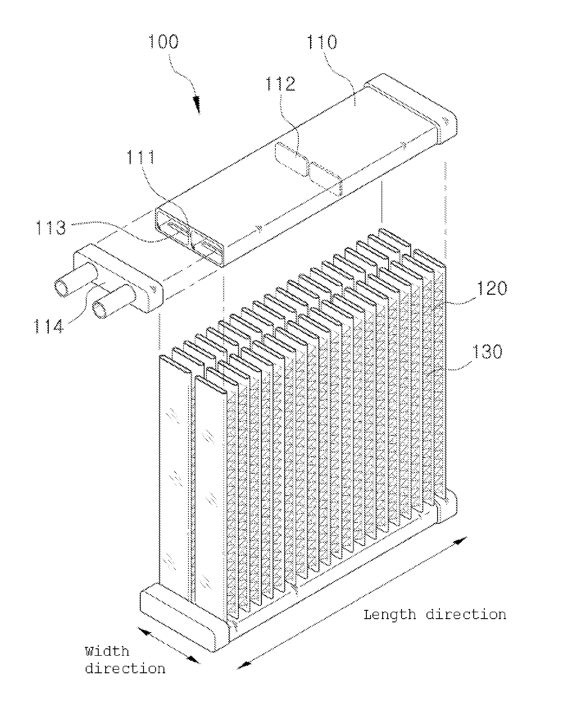
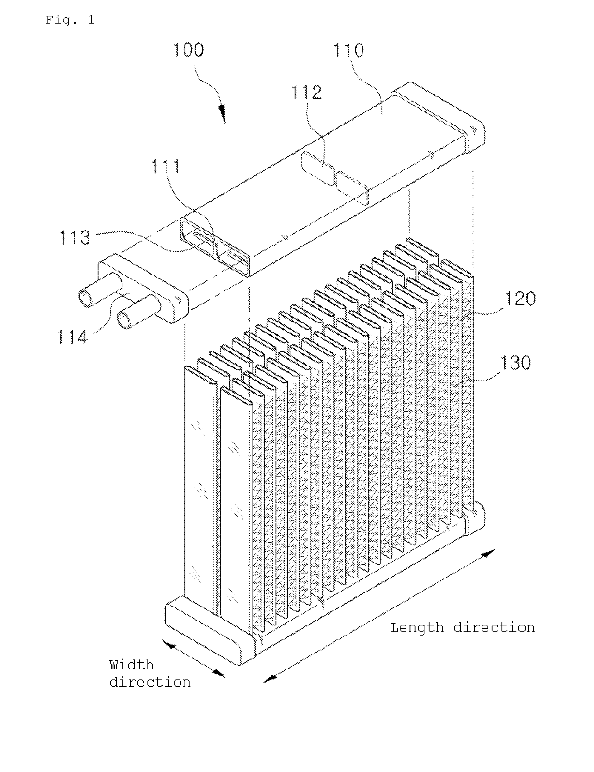
10: compressor11: condenser20: expanding means31: inlet port32a~32n: first to Nth discharging part33: inlet passage34a~34n: first to Nth outlet passage35: expanding part before branching35a~35n: first to Nth expanding parts40: evaporator41~4N: first to Nth evaporating part60: blower70: detecting means

BEST MODE

[0041]Hereinafter, the embodiments of the present invention will be described in detail with reference to accompanying drawings.

[0042]FIG. 3 is a view of a multi-evaporation system in accordance with the present invention. Like a general air-conditioning system, the multi-evaporation system of the present invention includes a compressor 10 which sucks and compresses refrigerant; a condenser 20 which condenses the refrigerant compressed in the compressor 10; an expanding means 30 which throttles the refrigerant condensed in the condenser 20; and an evaporator 40 which evaporates the refrigerant throttled in the expanding means 30. As shown in FIG. 3, the refrigerant discha...


PUM


Abstract

Provided is a multi-evaporation system which carries out a multi-evaporation process in an air-conditioning cycle of a vehicle air conditioning system, thereby enhancing system efficiency. The multi-evaporation system includes a compressor 10 which sucks and compresses refrigerant; a condenser 20 which condenses the refrigerant compressed in the compressor 10; an expanding means 30 which receives the refrigerant condensed in the condenser 20 through an inlet port 31, branches the refrigerant into at lest two or more, discharges the refrigerant through at least two or more discharging part 32a to 32n, and throttles the refrigerant before or after the refrigerant is branched; and an evaporator 40 which comprises at least two or more evaporating parts 41 to 4N so as to receive and evaporate the refrigerant discharged from the expanding means 30 and then introduce the evaporated refrigerant into the compressor 10.

Description

TECHNICAL FIELD [0001]The present invention relates to a multi-evaporation system, and more particularly, to a multi-evaporation system which carries out a multi-evaporation process in an air-conditioning cycle of a vehicle air conditioning system, thereby enhancing system efficiency.BACKGROUND ART[0002]In the automobile industry, as general concerns about energy and environment are increased globally, the efficiency in each part including fuel efficiency has been steadily improved, and the external appearance of a vehicle has been also diversified in order to satisfy various demands of customers. According to such a tendency, research and development on lighter weight, smaller size and multi-function of each vehicle component has been carried out. Particularly, in an air-conditioning unit for a vehicle, since it is generally difficult to secure an enough space in an engine room, there have been many efforts to manufacture an air-conditioning system having a small size and high effi...

Claims


Application Information

Patent Timeline
Patent Type & Authority Applications(United States)
IPC IPC(8): F25B41/04F25B1/06F25B39/02
CPCB60H1/323F25B5/02F28D2021/0085F25B2341/0661F28D1/05391F25B41/00F25B41/385
Inventor AHN, YONG NAMPARK, TAE YOUNGMIN, EUN GIKIM, DEOK SOO
Owner HANON SYST
Why Eureka
Try Eureka