Suspension liquid extraction apparatus and method

a suspension and liquid extraction technology, applied in lighting and heating equipment, multi-stage water/sewage treatment, separation processes, etc., can solve the problems of unprocessed suspensions, unprocessed suspensions typically cannot be disposed, and unprocessed suspensions are often difficult to transport and dispose of. , to achieve the effect of reducing the flow rate of air, widening the area and reducing the cost of transportation

Active Publication Date: 2010-08-26
GRYPHON ENVIRONMENTAL
View PDF108 Cites 14 Cited by
  • Summary
  • Abstract
  • Description
  • Claims
  • Application Information

AI Technical Summary

Benefits of technology

[0019]The second and additional chambers contain the filter and the conduit design of the first chamber. The vacuum and compressed and heated air of the second and additional chambers provide for the separation of the liquid from the solids of the suspension by providing for an efficient evaporation of interstitial and chemically bound liquids combined with a filter which allows for the liquids and vapor to pass, but prevents the solids of the suspension composition from passing there through. As the liquids and vapor pass through the filter, they are collected into the conduits and stored separately.
[0020]The primary benefit of the vacuum is that, at 23 inches of mercury (77.9 kPa) pressure, it reduces the boiling point to 146° F. (63.3° C.). Radiant heat, microwave radiation, and compressed heated air is applied to the suspension to heat the suspension to the boiling point. Compressed air provides for a lower flow rate of air to heat a larger area of the suspension. As the compressed air expands through atmospheric pressure, the heated air disperses to heat a wider area. The compressed air is continually injected from above. As the suspension begins to boil from the heat acting upon the reduced boiling point, the compressed air forces the water vapors through a filter and into the conduits to remove the liquids and vapors from the suspension. Microwave and radiant heat expedite the process.

Problems solved by technology

Mixtures of liquids and solids, known as suspensions, present expensive disposal problems to the industries that generate them.
Unprocessed suspensions typically cannot be disposed of in landfills due to regulations on water content.
Even with more permissive regulations, it is much more expensive to transport and dispose of unprocessed suspensions than just solid components because transportation charges and landfill charges correspond to weight.
Typically, the value of the dry solids arises from the decrease in weight occasioned by the removal of the liquid fraction, which leads to decreased disposal and transportation costs.
Unfortunately, efforts to work around the suspension disposal problems often employ methods lacking environmental soundness.
Aside from being a slow process, the potential for the pool lining to fail or result in contamination of the surrounding environment makes this a less-than-desirable solution in terms of both efficiency and environmental impact.
Industrial suspension ponds suffer from significant practical difficulties.
To begin, holding ponds have a poor resulting yield (dry solid percentage content).
Being passive, it also takes a long time to separate water from solids for a given volume of suspension, as compared to devices that rely on active separation.
Two active separation systems, centrifuge processors and belt presses, each produce higher solid content yields than suspension ponds., however, they lack the ability to utilize thermodynamics to achieve 60-100% dry solid percentage yields.
These active separation systems are expensive to purchase and operate and are not readily scaled up or down to handle corresponding volumes of industrial suspension flow rates.
The lack of portability and limitations on the amount of material which can be processed in a given time are also a significant limiting factor.

Method used


Image

  • Suspension liquid extraction apparatus and method
  • Suspension liquid extraction apparatus and method
  • Suspension liquid extraction apparatus and method

Examples


Embodiment Construction

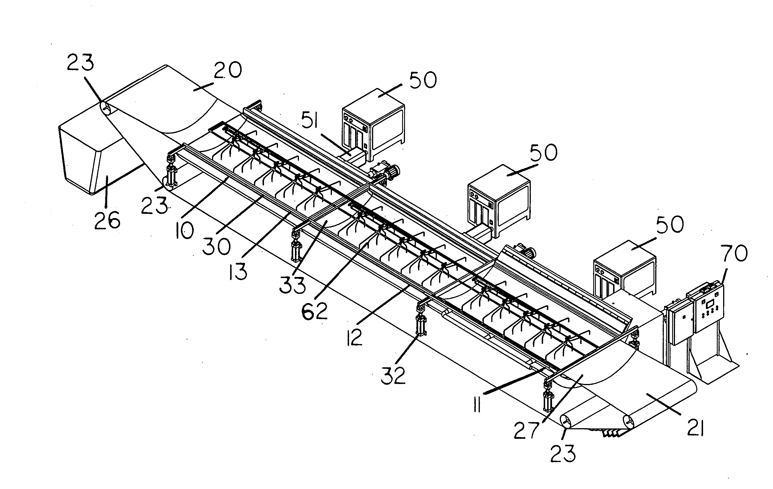
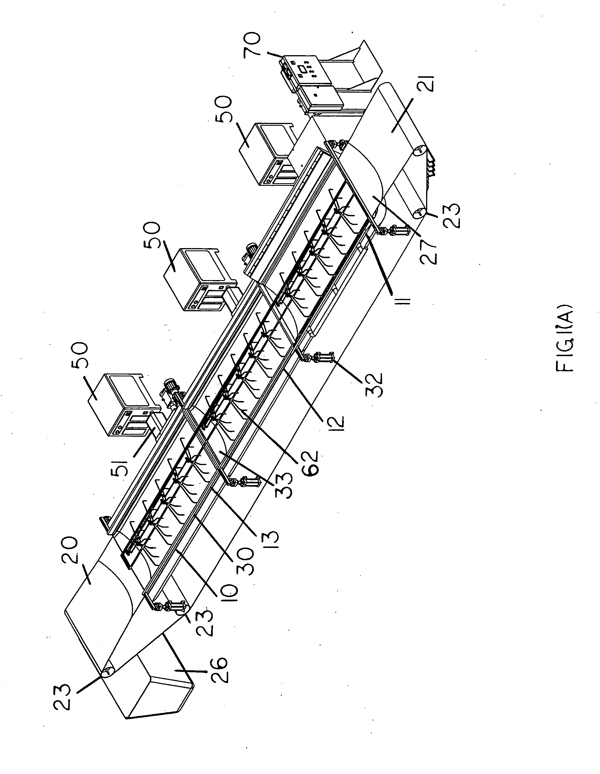
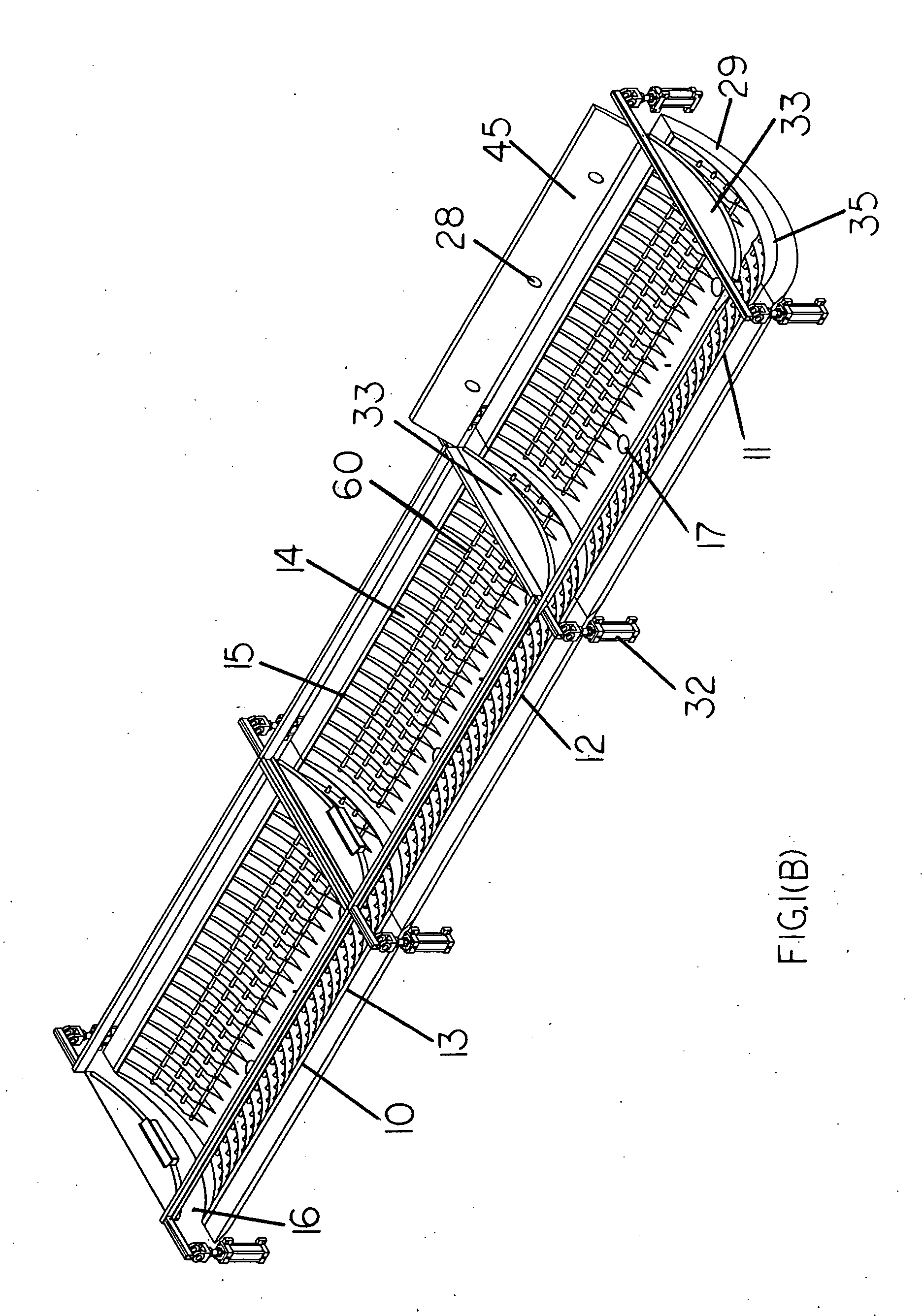
[0042]FIG. 1(a)-(c) depict one aspect of the invention, which includes a low profile, relatively compact and horizontal container 10, preferably arced or curved in shape, which may be further subdivided into serially linked chambers 11-13 for use at an industrial or municipal site that produces a suspension, such as, for example, a waste product or a mixture of liquids and solids. Although preferably arced, other designs may be readily apparent to those skilled in the art, such as, for example, a flat container. In a preferred embodiment, the container 10 is subdivided into three chambers 11-13. The container 10 may be buried in the ground or, alternatively, may be above ground and associated with a suitable frame, if necessary, to ensure stability. Still another option is to associate the container 10 with a vehicle, such as a flatbed truck or trailer, such that it may be easily transported from one site to another and thus becomes portable.

[0043]As noted above, the container 10 is...


PUM

PropertyMeasurementUnit
temperatureaaaaaaaaaa
pressureaaaaaaaaaa
pressureaaaaaaaaaa

Abstract

The present invention relates to an apparatus for removing liquid from a suspension. More particularly, the present invention relates to a filtration apparatus using vacuum pressure, compressed air and radiant heat to facilitate extraction of water from a suspension and an air flow within the vacuum chamber to remove the evaporate as a cost-efficient and resource-efficient means of filtering and drying solids in large volumes of suspension to remove interstitial and chemically bound liquids, resulting in up to 100% total solids.

Description

[0001]This application claims the benefit of U.S. provisional patent application Ser. No. 61 / 194,999, filed Oct. 2, 2008, titled Suspension Liquid Extraction Apparatus and Method.BACKGROUND OF THE INVENTION [0002](a) Field of the Invention[0003]The present invention relates to an apparatus for removing liquid from a suspension. More particularly, the present invention relates to a filtration apparatus using vacuum pressure, compressed air and radiant heat to facilitate extraction of water from a suspension and an air flow within the vacuum chamber to remove the evaporate as a cost-efficient and resource-efficient means of filtering and drying solids in large volumes of suspension to remove interstitial and chemically bound liquids, resulting in up to 100% total solids.[0004](b) Background of the Invention[0005]Mixtures of liquids and solids, known as suspensions, present expensive disposal problems to the industries that generate them. Unprocessed suspensions typically cannot be dis...

Claims


Application Information

Patent Timeline
Patent Type & Authority Applications(United States)
IPC IPC(8): B01D35/18B01D36/00B01D29/56B01D37/00
CPCB01D1/14C02F1/12C02F11/121C02F2209/005F26B17/04B01D2201/204B01D1/18B01D17/085F26B5/12B01D29/09C02F11/131
Inventor GRIFFIN, WILLIAM TID SMITHDEARMOND, JOSHUA MICHAEL-JAMES
Owner GRYPHON ENVIRONMENTAL
Why Eureka
Try Eureka