Liquid-level sensor

a liquid level sensor and liquid level technology, applied in liquid/fluent solid measurement, instruments, machines/engines, etc., can solve the problems of large scale and complex operation of liquid level calculation devices, and achieve the effect of accurate detection of liquid level and easy access to highly sensitive liquid level sensors

Inactive Publication Date: 2011-05-19
PANASONIC CORP
View PDF2 Cites 22 Cited by
  • Summary
  • Abstract
  • Description
  • Claims
  • Application Information

AI Technical Summary

Benefits of technology

[0013]The present invention provides a liquid level sensor which can accurately detect a liquid level without a complex operational device even though a dielectric constant or a temperature of a liquid to be measured changes.
[0014]A liquid level sensor according to the present invention includes a detecting unit having a first detecting electrode always being in a liquid to be measured, a second detecting electrode which measures a liquid level of the liquid to be measured, and a third detecting electrode always being out of the liquid to be measured; and a circuit which repeats an operation of charging for a time which is in proportion to a ratio of a length of a part of the second detecting electrode dipped in the liquid to be measured to a total length of the second detecting electrode and an operation of discharging the charged electric charge for a time which is in proportion to a ratio of a length of a part of the second detecting electrode being out of the liquid to be measured to the total length of the second detecting electrode. With this configuration, a voltage being in proportion to a liquid level can be always outputted without arranging a complex operational device even though a dielectric constant, a temperature, or the like of the liquid to be measured changes. For this reason, a highly sensitive liquid level sensor can be easily provided.

Problems solved by technology

Therefore, an operational device to calculate the liquid level becomes complex and has a large scale.

Method used


Image

  • Liquid-level sensor
  • Liquid-level sensor
  • Liquid-level sensor

Examples


embodiment 1

[0111]A liquid level sensor according to Embodiment 1 of the present invention will be described below with reference to the accompanying drawings.

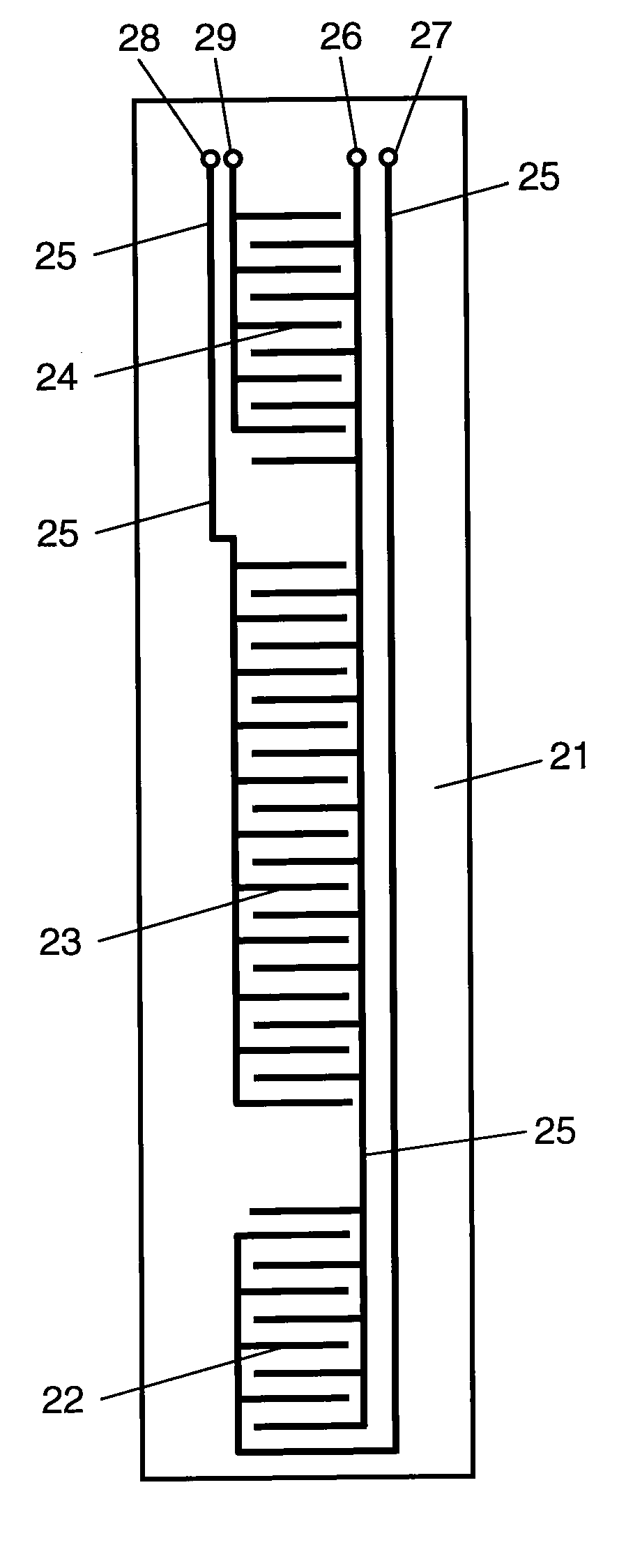
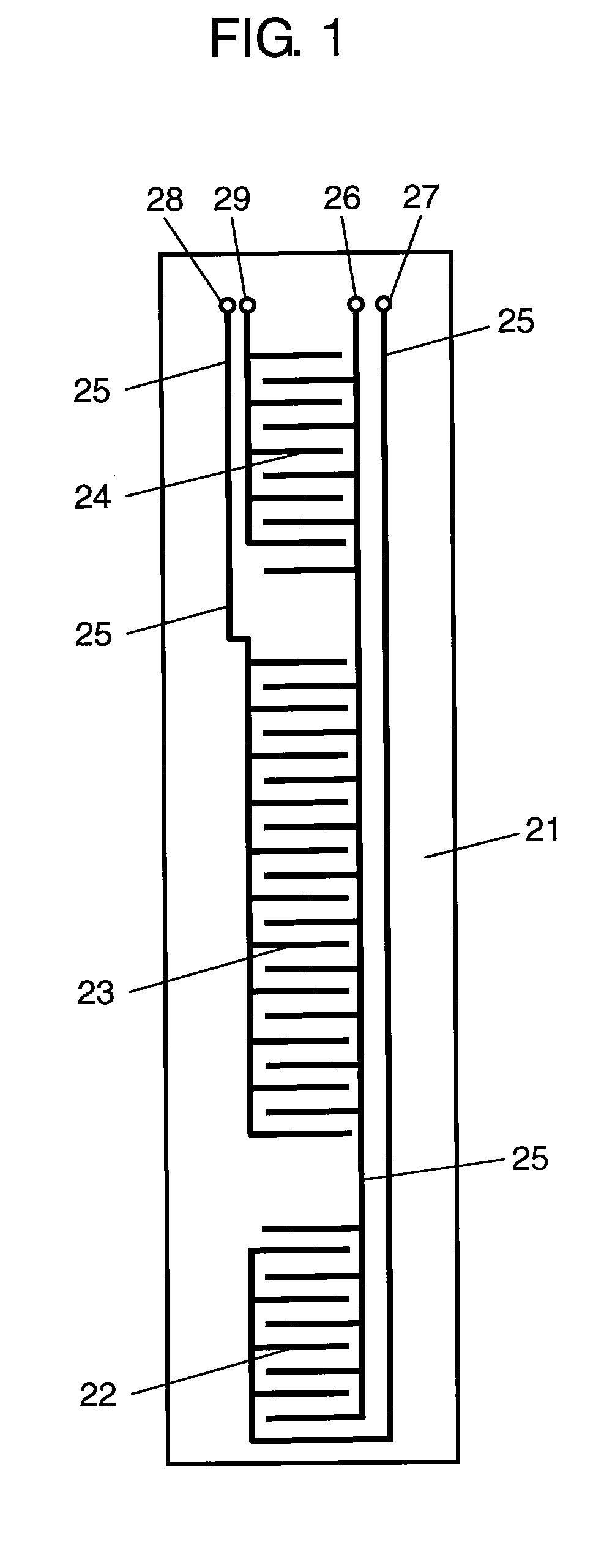
[0112]FIG. 1 is a front view of a detecting unit in the liquid level sensor according to Embodiment 1 of the present invention. In FIG. 1, a pair of first comb-shaped detecting electrodes 22 made of carbon are arranged on a lower end portion of vertically extending rectangular detecting unit 21 made of a polyimide film or the like. A pair of second comb-shaped detecting electrodes 23 made of carbon are arranged at the center of detecting unit 21. Furthermore, similarly, a pair of third comb-like detecting electrodes 24 made of carbon are arranged on an upper end portion of detecting unit 21. First, second, and third detecting electrodes 22, 23, and 24 are connected to terminals 26, 27, 28, and 29 with vertically extending extraction lines 25.

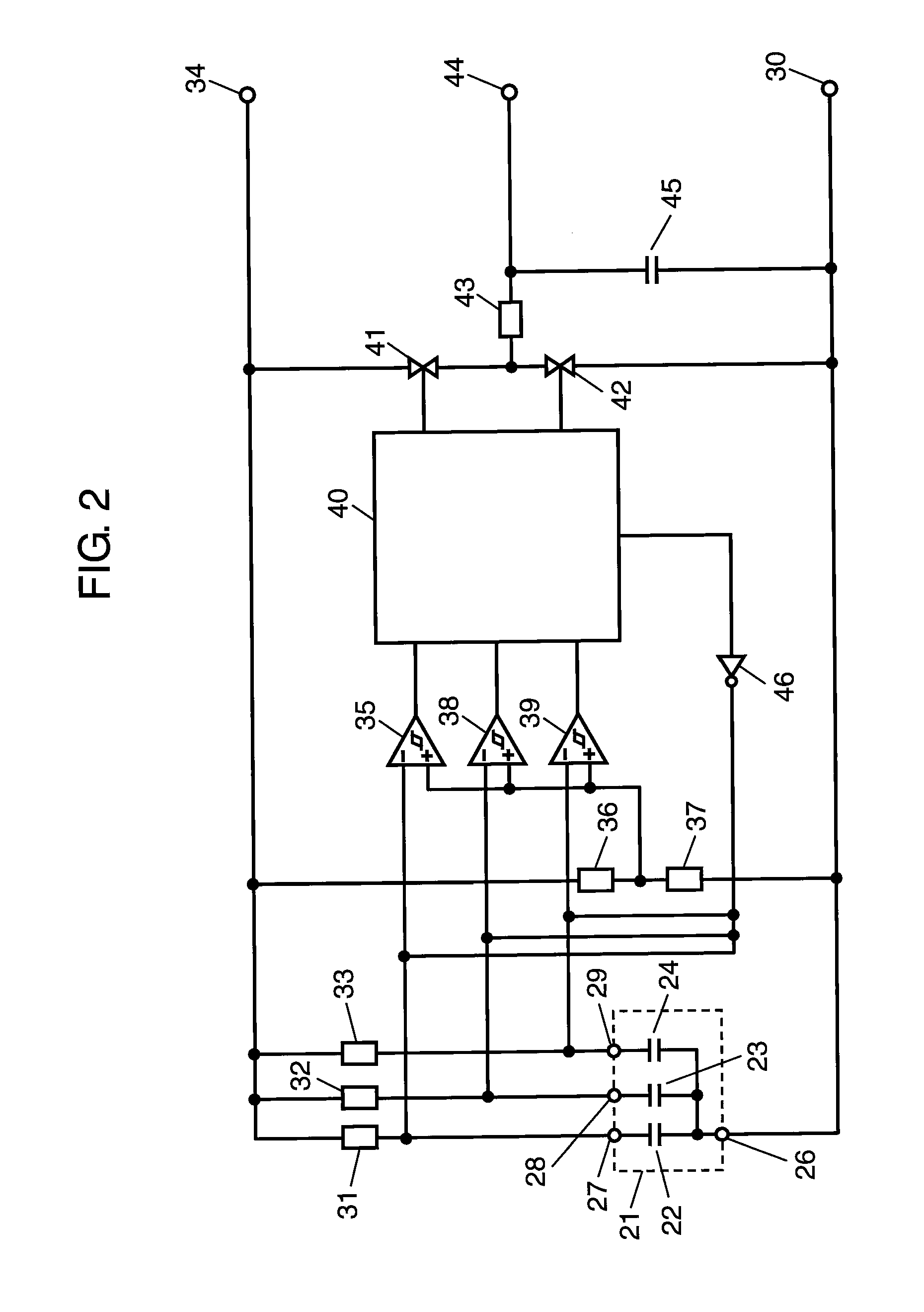
[0113]FIG. 2 is a detecting circuit diagram of the liquid level sensor according to Embodiment 1 o...

embodiment 2

[0157]A liquid level sensor according to Embodiment 2 of the present invention will be described below with reference to the accompanying drawings.

[0158]FIG. 8 is a front view of a detecting unit of the liquid level sensor according to Embodiment 2 of the present invention. In FIG. 8, a pair of first comb-shaped detecting electrodes 222 made of carbon are arranged on a lower end portion of vertically extending rectangular detecting unit 221 made of a polyimide film or the like. A pair of second comb-shaped detecting electrodes 223 made of carbon are arranged at the center of detecting unit 221. Furthermore, similarly, a pair of third comb-shaped detecting electrodes 224 made of carbon are arranged on an upper end portion of detecting unit 221. First, second, and third detecting electrodes 222, 223, and 224 are connected to terminals 229, 230, 231, and 232 by common extraction line 225 and extraction lines 226, 227, and 228 which vertically extend. First cancel electrode 233 arranged...

embodiment 3

[0208]A liquid level sensor according to Embodiment 3 of the present invention will be described below.

[0209]FIG. 15 is a front view of a detecting unit in the liquid level sensor according to Embodiment 3 of the present invention. In FIG. 15, a pair of first comb-shaped detecting electrodes 322 made of carbon are arranged on a lower portion of vertically extending rectangular detecting unit 321 made of a polyimide film or the like. Above first detecting electrodes 322, a pair of second comb-shaped detecting electrodes 323 made of carbon are arranged. Above second detecting electrodes 323, similarly a pair of third comb-shaped detecting electrodes 324 made of carbon are similarly arranged. Further, a pair of fourth comb-shaped detecting electrodes 325 made of carbon are similarly arranged on a lower end portion of detecting unit 321. First, second, third, and fourth detecting electrodes 322, 323, 324, and 325 are connected to terminals 326, 327, 328, 329, and 330 with vertically ext...


PUM


Abstract

In a liquid level sensor according to the present invention, a first detecting electrode being always in a liquid to be measured, a second detecting electrode which measures a level of the liquid to be measured, and a third detecting electrode being always out of the liquid to be measured are arranged, an operation of charging capacitor 45 for a time being in proportion to a ratio of a length of a part of the second detecting electrode in the liquid to be measured to a total length of the second detecting electrode and an operation of discharging the electric charge of the capacitor for a time being in proportion to a ratio of a length of a part of the second detecting electrode being out of the liquid to be measured to the total length of the second detecting electrode is repeated. With this configuration, the liquid level can be precisely detected without arranging a complex operational device even though a dielectric constant or a temperature of the liquid to be measured changes.

Description

TECHNICAL FIELD[0001]The present invention relates to a liquid level sensor which detects a liquid level of a liquid stored in a vessel and, in particular, to a liquid level sensor which detects a liquid level of an engine oil or a fuel for an automobile, a construction machine, or the like.BACKGROUND ART[0002]As a liquid level sensor which detects a liquid level of an engine oil or a fuel in an automobile, a construction machine, or the like, a liquid level sensor as shown in FIG. 33 or 34 is known (see Patent Document 1).[0003]FIG. 33 is a front view of a detecting unit of a conventional liquid level sensor. In FIG. 33, first comb-shaped detecting electrode unit 2 is arranged on a lower end portion of rectangular substrate 1 which vertically extends. Second comb-shaped detecting electrode unit 3 is arranged on a central portion of substrate 1.[0004]First detecting electrode unit 2 is configured by a plurality of linear electrodes 4 vertically arranged at predetermined intervals. L...

Claims


Application Information

Patent Timeline
Patent Type & Authority Applications(United States)
IPC IPC(8): G01F23/26
CPCG01F23/268G01F23/266
Inventor OHSHIMA, MIKIHIROOGATA, MOTOKITAKASHIMA, YOSHINORIKASHIWAGI, TAKESHI
Owner PANASONIC CORP
Why Eureka
Try Eureka