Apparatus for reducing drag on vehicles with planar rear surfaces

a rear surface and apparatus technology, applied in the direction of roofs, vehicle arrangements, transportation and packaging, etc., can solve the problems of reducing fuel economy, requiring a sizable replacement cost, and devices with certain drawbacks, so as to reduce or prevent the formation of a volume of turbulent air

Inactive Publication Date: 2011-05-19
SKOPIC JOSEPH
View PDF132 Cites 45 Cited by
  • Summary
  • Abstract
  • Description
  • Claims
  • Application Information

AI Technical Summary

Benefits of technology

[0018]The vane reduces or prevents formation of a volume of turbulent air between the first and second vehicles. In various embodiments, the first and second supports rigidly connect the side surface of the first vehicle to the vane. In various embodiments, one vane is mounted on each side of the vehicle.
[0021]Various embodiments relate to an apparatus for affecting airflow around a first moving vehicle towing or being pushed by a second vehicle. The first moving vehicle has a substantially planar rear surface. The apparatus comprises a rigid horizontal vane having a leading edge, a trailing edge, and a lower surface; and at least one support connecting said lower surface of said vane to a top surface of said first vehicle. The vane reduces or prevents formation of a volume of turbulent air above the rear surface of the first moving vehicle.

Problems solved by technology

A vehicle is then required to expend energy to push this volume of air aside, thereby reducing fuel economy.
A second, and at least equally pernicious, form of resistance to a vehicle in motion lies in the drag on the vehicle caused by the formation of turbulent zones at the rear of the vehicle, or in between units of a combination vehicle, such as a string of multiple trailers.
However, due to turbulence caused by the passage of the vehicle, a space filled with low pressure air forms between the rear of the vehicle and the point at which these airstreams fully recombine.
However, a number of legacy trailers exist; which would require a sizable expense to replace.
However, these devices do have certain drawbacks.
Thus, these devices may not be simply mounted on a trailer and left in place.
Similarly, such devices must be disassembled and removed from the trailer before unloading can begin, causing inconvenient delays in the unloading and loading processes.
Another drawback of using rear-mounted devices on trailers is that the devices add significantly to the length of a trailer, making it difficult to use these conical or pyramidal devices to reduce drag in between a pair of trailers mounted in series.
Some designs allow the vanes to slide into or out of tracks mounted on the side of the vehicle; while the use of such tracks accelerates the process of positioning vanes after loading and unloading the trailer, the cost and complexity of retrofitting an existing trailer with a streamlined vane is significantly increased.
However, in the case of a vehicle having hinged doors, these boattail plates impede the doors from swinging open.
In the case of a vehicle having a roll-up door, these boattail plates impede the vehicle from backing up to a loading dock.
As a result, boattail plates have not achieved wide acceptance.
While these do an effective job of preventing drag, they do impede opening the doors on the rear of the trailer.
The inability to fully open the vehicle doors is a problem during the loading / unloading process, particularly when backing into docks that are located in confined spaces.

Method used


Image

  • Apparatus for reducing drag on vehicles with planar rear surfaces
  • Apparatus for reducing drag on vehicles with planar rear surfaces
  • Apparatus for reducing drag on vehicles with planar rear surfaces

Examples


Embodiment Construction

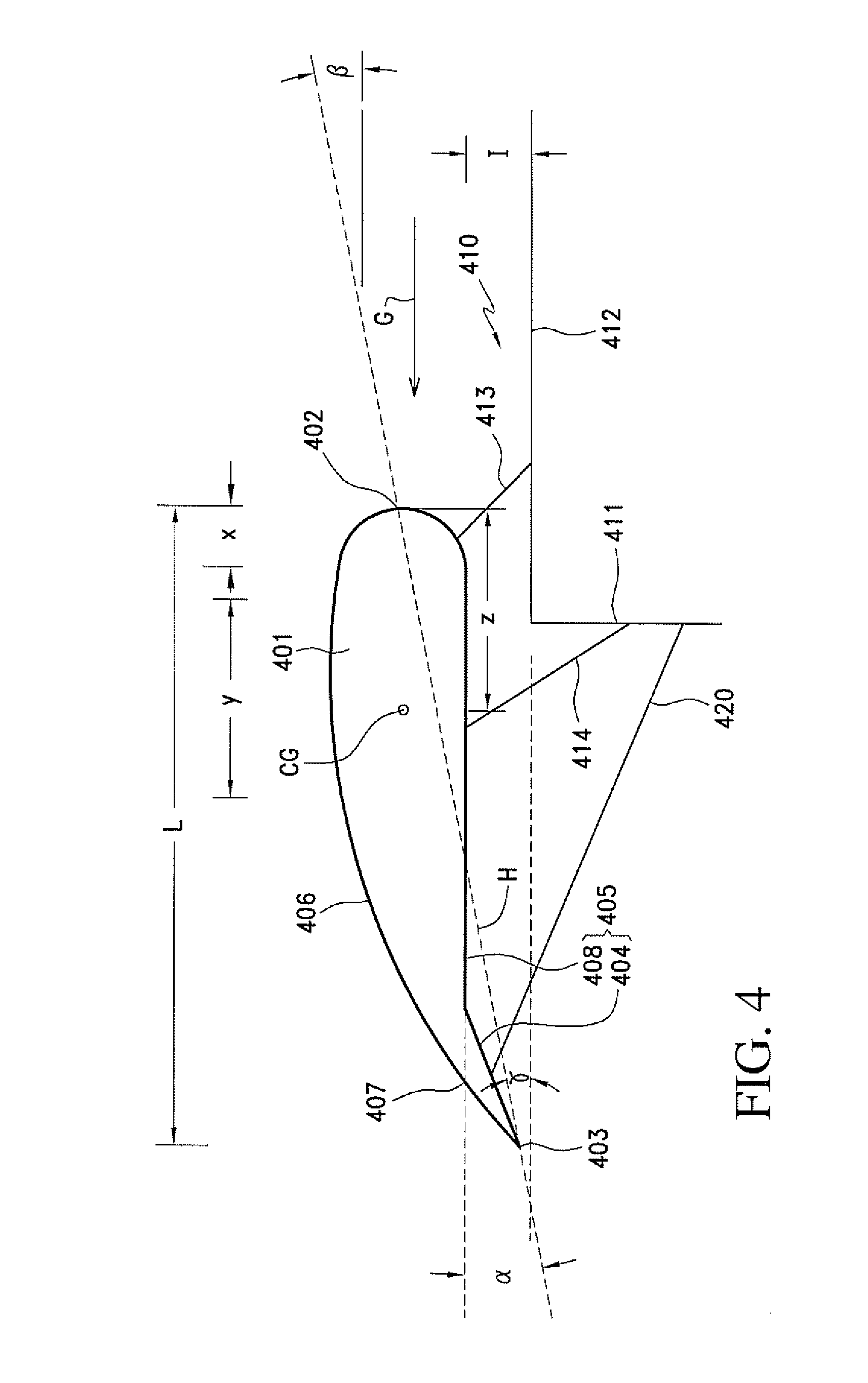
[0043]The term “aerodynamic center,” as used in this disclosure, may be defined as, but is not limited to, the point at which the pitching moment coefficient for a vane or airfoil does not vary with lift coefficient. For symmetric vanes or airfoils moving through an airflow, the aerodynamic center of the vane is located approximately 25% of the length of the chordline of the vane from the leading edge of the vane (the quarter-chord point). The chordline extends from the leading edge of the airfoil to the trailing edge of the vane or airfoil. For non-symmetric (cambered) vanes, the quarter-chord is only an approximation for the aerodynamic center.

[0044]The term “tractor,” as used in this disclosure, may be defined as, but is not limited to, a motor-driven vehicle used for pulling heavy machinery or other vehicles. In various embodiments, the term “tractor” relates to a truck tractor; i.e., a short truck with a driver's cab but no body, designed for hauling a trailer or semitrailer.

[0...


PUM


Abstract

Vanes are used for reducing drag on a first vehicle having a substantially planar rear surface, where the first vehicle is used to tow an unpowered second vehicle. Rigid brackets or braces may be used to mount vanes to the first vehicle. The apparatus is extremely light weight, and includes a rigid vane of length L having a leading edge and a trailing edge. The vane has an inner surface facing the vehicle and an outer surface. A first rigid bracket or brace and a second rigid bracket or brace may connect the upper and lower ends of the vane to a side surface of the first vehicle, respectively. The vane prevents or reduces formation of a zone of turbulent air between the first and second vehicles by directing airflow away from an airspace between the first and second vehicles. The apparatus allows substantial reductions in fuel consumption. The apparatus also reduces tractor CO2 emissions during use as a result of reduced fuel consumption.

Description

CROSS-REFERENCE TO RELATED APPLICATIONS[0001]This application is a continuation-in-part application of U.S. application Ser. No. 12 / 398,643, filed on Mar. 5, 2009.BACKGROUND OF THE INVENTION[0002]1. Field of the Invention[0003]The invention relates generally to devices for reducing air flow resistance and drag on trucks, semitrailers, railway cars, and other vehicles. More particularly, the invention relates to devices for redirecting air from airstreams passing around a vehicle into zones of turbulent air at the rear of the vehicle.[0004]2. Description of the Prior Art[0005]The profitability of long-distance highway cargo transport depends heavily on the cost of fuel, and on the efficiency with which the fuel is utilized. The cost of fuel is largely outside the control of the cargo transporter; however, the efficiency of fuel utilization may be increased. One method involves reducing resistance to forward motion of a vehicle through the air, Resistance to vehicular motion takes two...

Claims


Application Information

Patent Timeline
Patent Type & Authority Applications(United States)
IPC IPC(8): B62D35/00
CPCB62D35/001
Inventor SKOPIC, JOSEPH
Owner SKOPIC JOSEPH
Why Eureka
Try Eureka