Long life power supply

Inactive Publication Date: 2011-05-19
S3J ELECTRONICS
View PDF10 Cites 9 Cited by
  • Summary
  • Abstract
  • Description
  • Claims
  • Application Information

AI Technical Summary

Benefits of technology

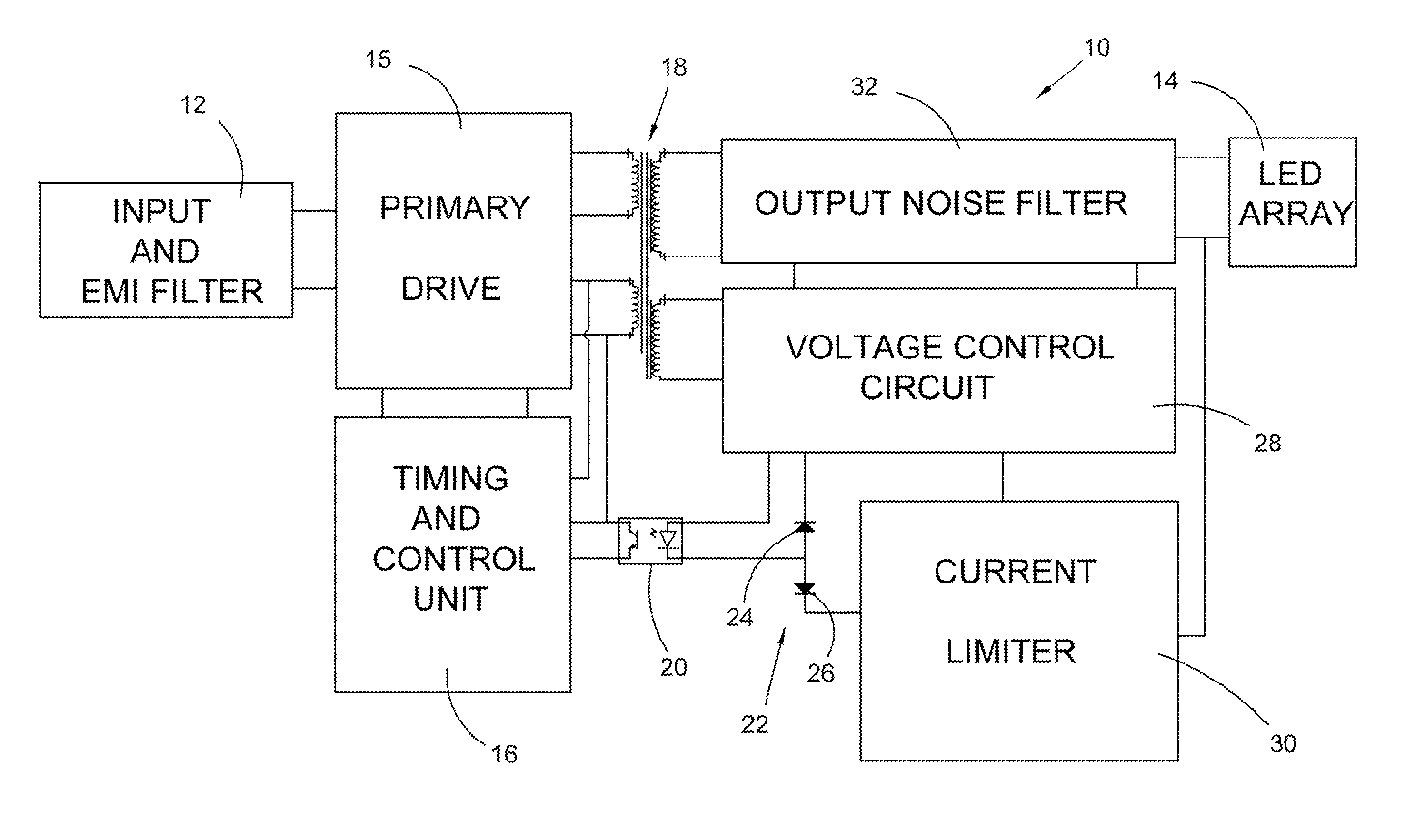
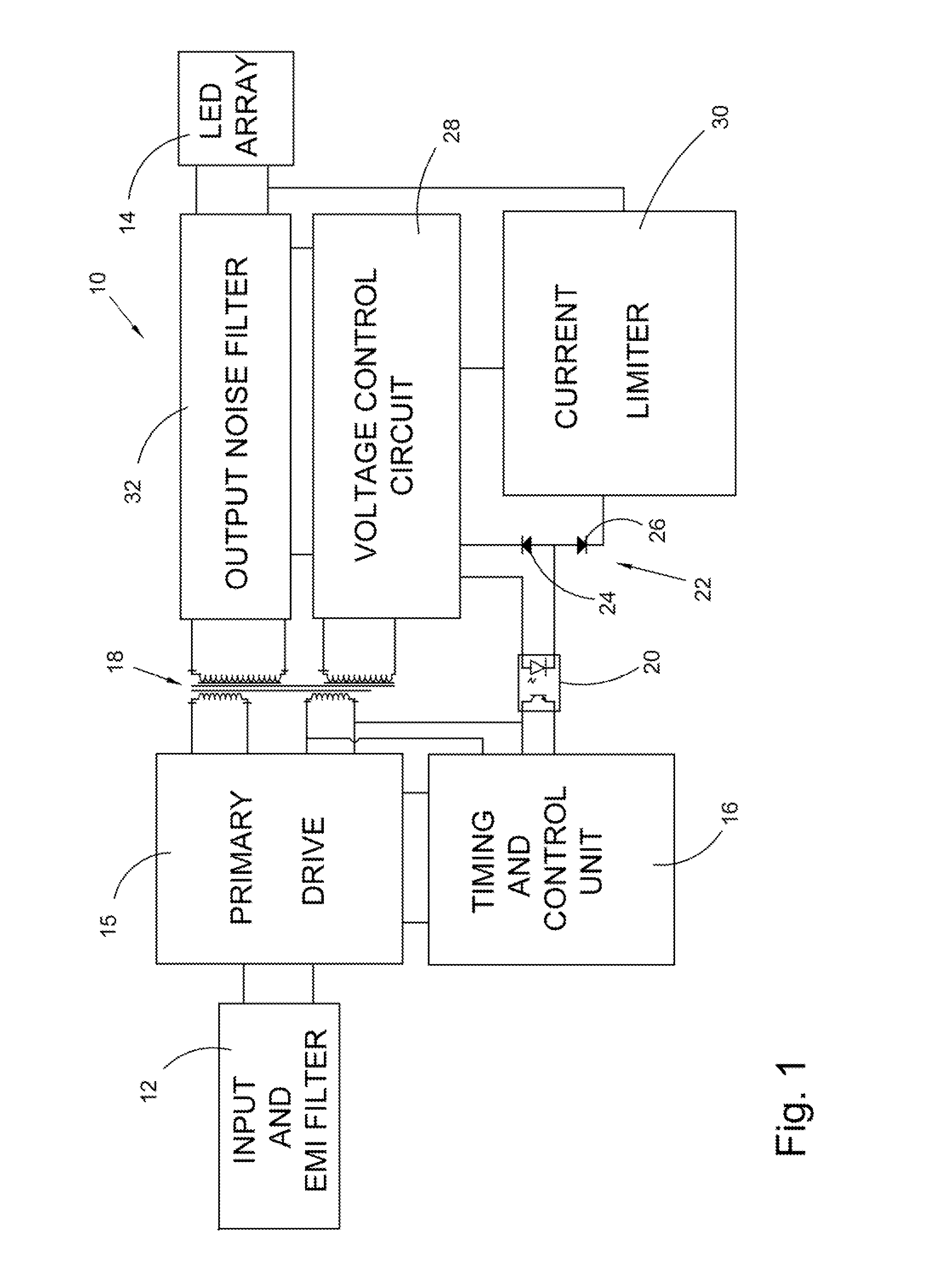
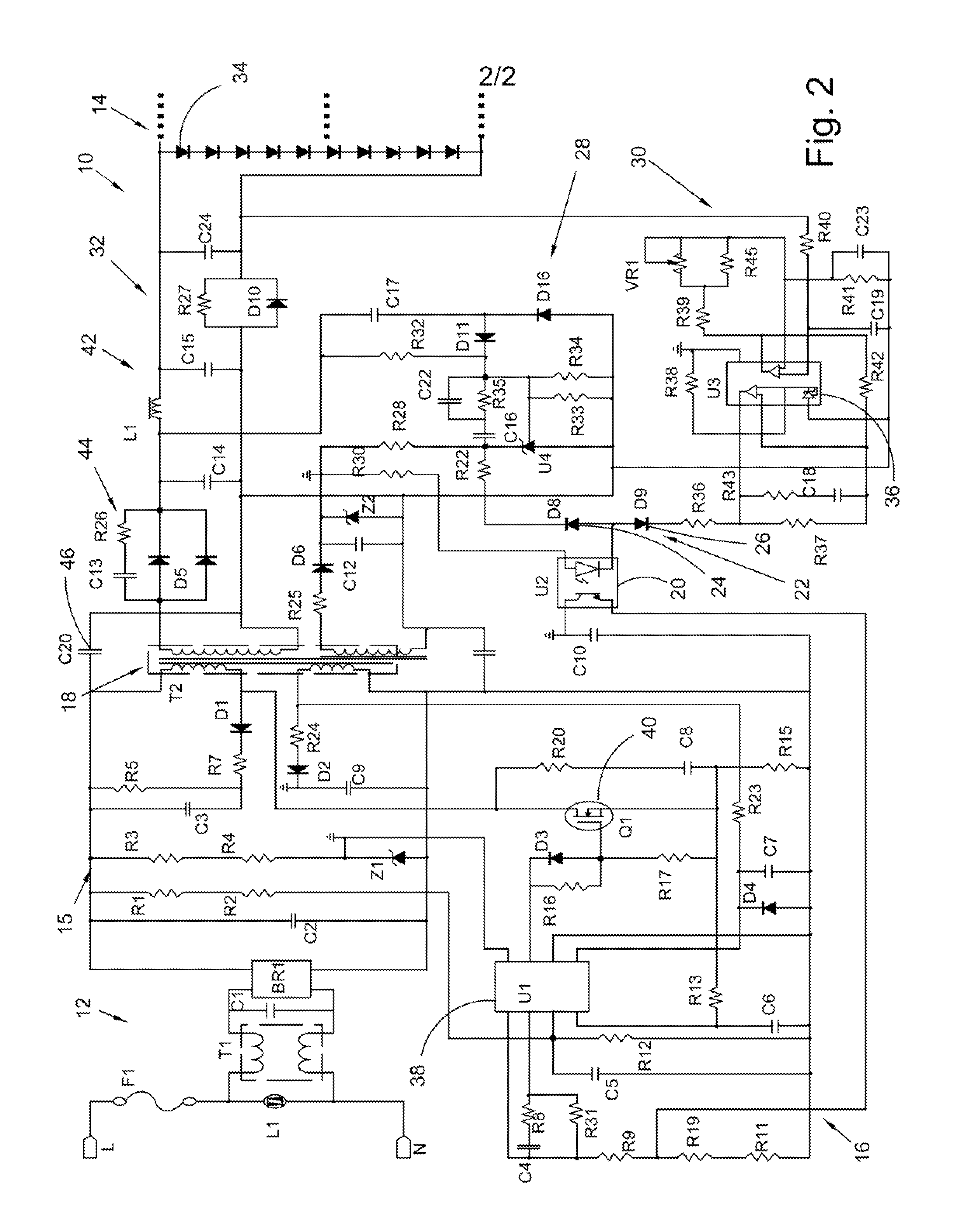
[0011]The current invention broadly comprises an LED driver for at least one light emitting diode including an input for receiving an input voltage, an output comprising at least one light emitting diode, a current limiting loop for regulating an output current supplied to the at least one light emitting diode, a voltage control loop for monitoring a feedback voltage from the at least one light emitting diode, and a junction including a first diode for closing the current limiting loop and a second diode for closing the voltage control loop, wherein the junction enables the voltage control loop to communicate with the current limiting loop such that the feedback voltage is taken into account by the current limiting loop in regulating the out current.
[0012]In one embodiment, the LED driver further comprises a timing unit for controlling an operating frequency of the LED driver. In another embodiment, the timing unit is isolated from both the voltage control loop and the current limiting loop via at least one transformer. In one embodiment, the LED driver further comprises an optocoupler connected to the voltage control loop, the junction, and the timing unit, wherein the optocoupler is operatively arranged to send a signal from the voltage control loop to the timing unit if the voltage control loop determines that an unnecessarily high voltage is being applied to the at least one light emitting diode

Problems solved by technology

However, these systems do not monitor or control the voltage to the output LED array.
However, Wang does not disclose a device which controls both voltage and current in the same device; the voltage controlled device in Wang is specifically arranged for use with OLEDs, while the current controlled device is specifically arranged for use with WLEDs.
Furthermore, for example, if a traditional LED array is used in which current controls brightness, and one of the LEDs burns or blows out, then the voltage applied to the remaining LEDs in the array would become unnecessarily high, since there would be no voltage drop over the burned out LED.
However, despite the seemingly proper functioning of the LEDs, this unnecessary increase in voltage would likely lead to premature burn out of the remaining LEDs, thereby shortening the lifespan of the LED array.
However, the lifespan of e-caps is often limited, unless under idea

Method used


Image

  • Long life power supply
  • Long life power supply
  • Long life power supply

Examples


Embodiment Construction

[0017]At the outset, it should be appreciated that like drawing numbers on different drawing views identify identical, or functionally similar, structural elements of the invention. While the present invention is described with respect to what is presently considered to be the preferred aspects, it is to be understood that the invention as claimed is not limited to the disclosed aspects.

[0018]Furthermore, it is understood that this invention is not limited to the particular methodology, materials and modifications described and as such may, of course, vary. It is also understood that the terminology used herein is for the purpose of describing particular aspects only, and is not intended to limit the scope of the present invention, which is limited only by the appended claims.

[0019]Unless defined otherwise, all technical and scientific terms used herein have the same meaning as commonly understood to one of ordinary skill in the art to which this invention belongs. It should be appr...


PUM


Abstract

An LED driver for at least one light emitting diode including an input for receiving an input voltage, an output comprising at least one light emitting diode, a current limiting loop for regulating an output current supplied to the at least one light emitting diode, a voltage control loop for monitoring a feedback voltage from the at least one light emitting diode, and a junction including a first diode for closing the current limiting loop and a second diode for closing the voltage control loop, wherein the junction enables the voltage control loop to communicate with the current limiting loop such that the feedback voltage is taken into account by the current limiting loop in regulating the out current.

Description

CROSS-REFERENCE TO RELATED APPLICATIONS[0001]This patent application claims the benefit under 35 U.S.C. §119(e) of U.S. Provisional Patent Application No. 61 / 262,001, filed Nov. 17, 2009, which application is incorporated herein by reference.FIELD OF THE INVENTION[0002]The invention broadly relates to lighting systems, more specifically to light emitting diodes (LEDs), and even more particularly to a long life power supply for driving one or more LEDs.BACKGROUND OF THE INVENTION[0003]LEDs are becoming increasingly popular in a wide range of lighting applications due to their long lifespan and high efficiency when compared to traditional lighting systems, such as incandescent bulbs or gas-discharge lamps. The longer lifespan and higher efficiency makes them not only cheaper to maintain, but also results in less impact on the environment in terms of power consumption.[0004]The brightness of traditional LEDs (also known as white light-emitting diodes, or WLEDs) is determined by the cur...

Claims


Application Information

Patent Timeline
IPC IPC(8): H05B37/02
CPCH05B33/0815H05B33/0809H05B45/382
Inventor FANNIN, JAMIE
Owner S3J ELECTRONICS
Why Eureka
Try Eureka