System and Method for Aligning a Rotor to a Known Position

a technology of rotor and known position, which is applied in the direction of motor/generator/converter stopper, dynamo-electric converter control, stopping arrangement, etc., can solve the problems of reducing efficiency, maintenance issues, and friction in the motor, so as to improve efficiency, reduce power, and improve motor performance

Inactive Publication Date: 2011-05-19
MICROCHIP TECH INC
View PDF29 Cites 25 Cited by
  • Summary
  • Abstract
  • Description
  • Claims
  • Application Information

AI Technical Summary

Benefits of technology

[0028]The above methods provide significantly greater motor performance, e.g., increased efficiency, as compared to prior art designs. In particular, the above methods more accurately place the rotor in a known position, in a wa

Problems solved by technology

The use of brushes creates friction in the motor and leads to maintenance issues and reduced efficiency.
One issue that arises when using BEMF detection is that if the rotor is not moving, there is no BEMF to be detected.
Both of these techniques leave much to be desired.
This is an energy intensive way to align a rotor, and has the potential to damage motor windings.
In addition, motor braking techniques typically do not consider the possibility of placing the rotor in a position condu

Method used


Image

  • System and Method for Aligning a Rotor to a Known Position
  • System and Method for Aligning a Rotor to a Known Position
  • System and Method for Aligning a Rotor to a Known Position

Examples


Embodiment Construction

FIGS. 1A and 1B—Exemplary Fan and Fan Motor

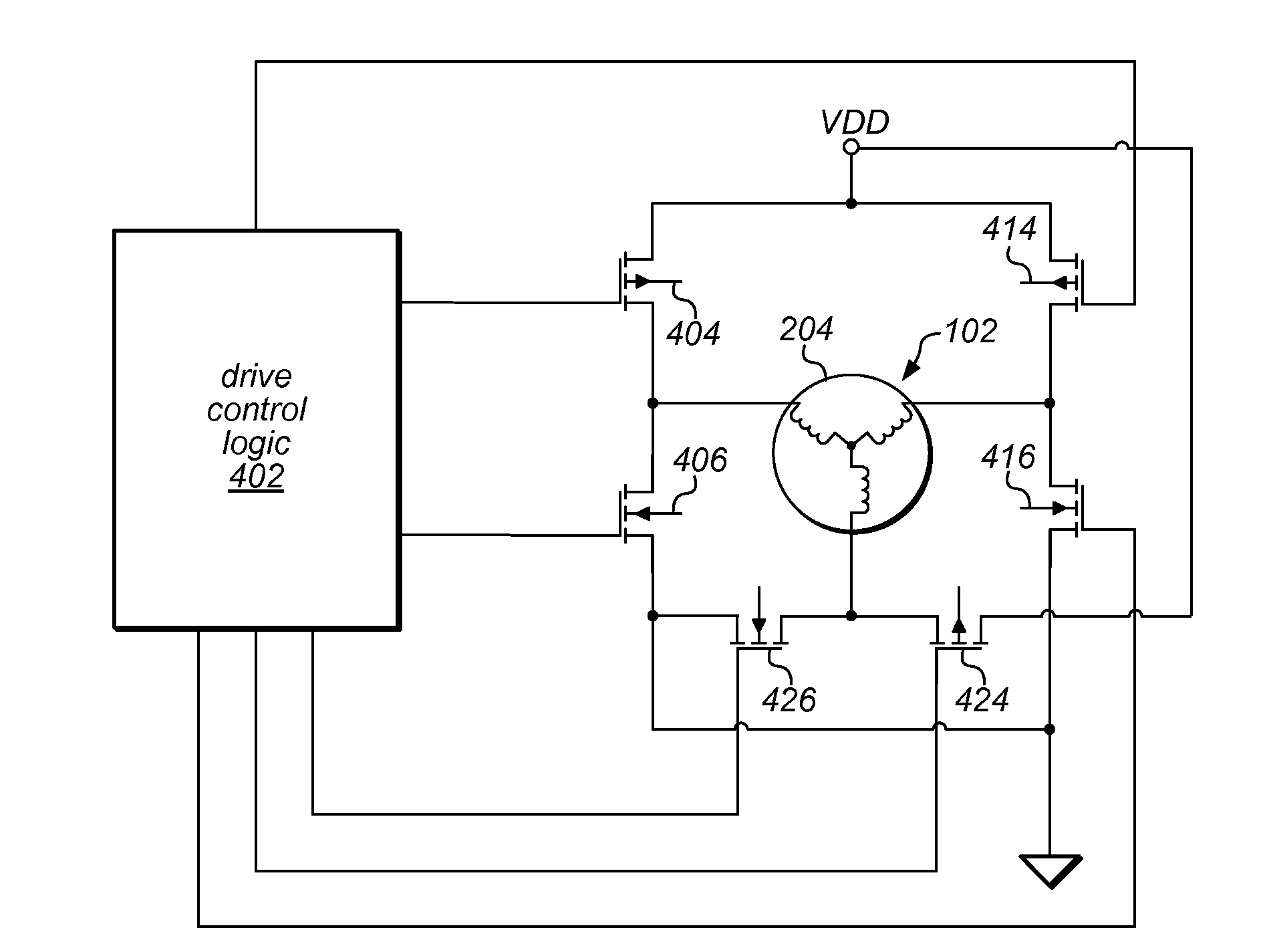
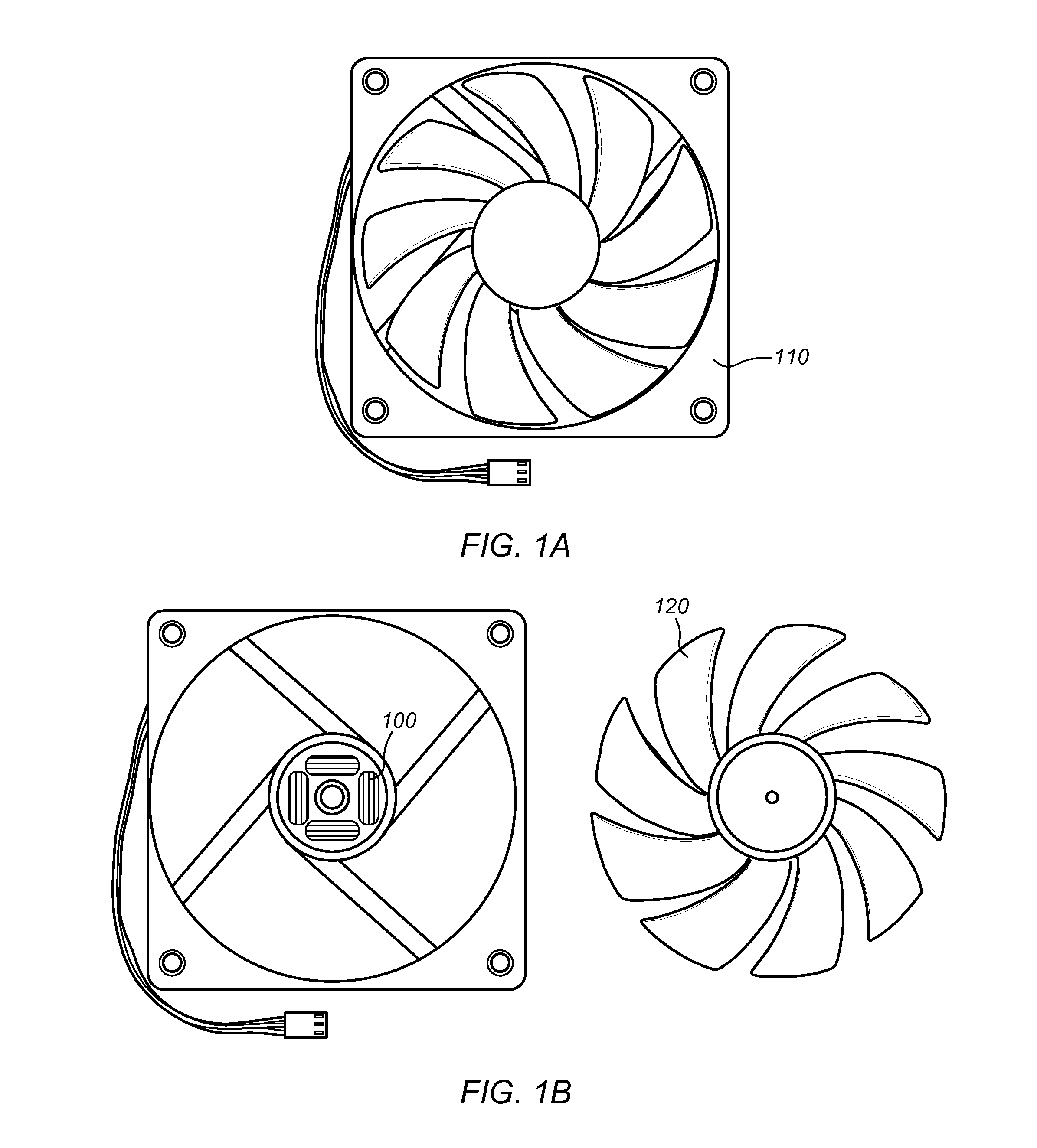
[0038]FIGS. 1A and 1B illustrate an exemplary fan assembly 110 according to one embodiment. The fan 110 may be a cooling fan, for example a fan for use in a laptop or a desktop computer. The fan 110 may alternatively be a commercial or industrial fan, or in general any type of fan driven by a motor. The fan assembly 110 may include a motor assembly 100 as well as fan blades 120. The motor assembly 100 may comprise a motor (102, FIG. 2) as well as drive circuitry (402FIG. 4) for controlling the motor 102.

[0039]Although FIGS. 1A and 1B illustrate a fan as the load being driven by the motor, it should be noted that the system and method for aligning a rotor to a known position as described herein may be suited for driving any of various types of loads, including without limitation hard disk drives, drive motors for appliances, propellers, wheels, pumps, or other loads.

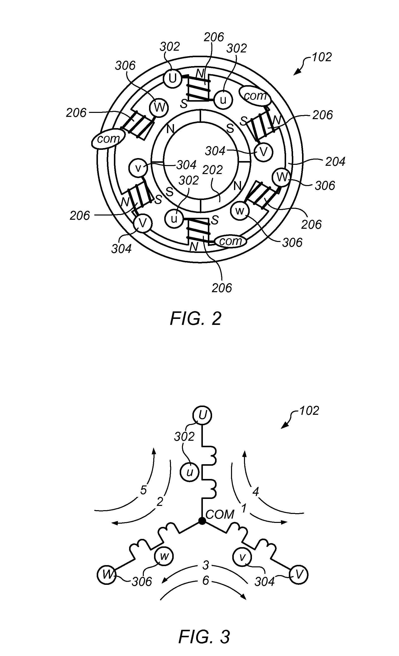
FIG. 2—Brushless Four-Pole Three-Phase Motor

[0040]FIG. 2 illustrates a simpl...


PUM


Abstract

A system and method are presented for aligning a rotor in a motor. The motor may include the rotor and a plurality of pairs of electromagnets. One or more pairs of electromagnets may be excited at a first excitation level. The one or more pairs of electromagnets may be less than all of the plurality of pairs of electromagnets. The excitation of the one or more pairs of electromagnets may be increased to a second excitation level over a first period of time. The excitation of the one or more pairs of electromagnets may be decreased to a third excitation level over a second period of time. Exciting the one or more pairs of electromagnets, increasing the excitation, and decreasing the excitation may cause the rotor to stop in a known position.

Description

INCORPORATION BY REFERENCE[0001]U.S. patent application Ser. No. 12 / 393,996 titled “Brushless, Three Phase Motor Drive”, filed on Feb. 26, 2009, whose inventors are Lynn R. Kern and James P. McFarland, is hereby incorporated by reference as though fully and completely set forth herein.[0002]U.S. patent application Ser. No. 12 / 620,656, titled “System and Method for Inducing Rotation of a Rotor in a Sensorless Motor”, filed on Nov. 18, 2009, whose inventors are Lynn R. Kern and James P. McFarland, is hereby incorporated by reference as though fully and completely set forth herein.[0003]U.S. patent application Ser. No. ______, titled “Brushless, Three Phase Motor Drive”, filed on Nov. 18, 2009, whose inventors are Lynn R. Kern, Scott C. McLeod, and Ken Gay, is hereby incorporated by reference as though fully and completely set forth herein.BACKGROUND OF THE INVENTION[0004]1. Field of the Invention[0005]The invention generally relates to DC (Direct Current) motors used in various applic...

Claims


Application Information

Patent Timeline
IPC IPC(8): H02P6/24
CPCH02P6/205H02P6/24H02P6/21
Inventor KERN, LYNN R.
Owner MICROCHIP TECH INC
Why Eureka
Try Eureka