Polarization element and projector

a technology applied in the field of polarizing elements and projectors, can solve the problems of affecting the display quality, affecting the quality of the image, and affecting the quality of the image, and achieve the effect of excellent display

Active Publication Date: 2011-05-19
SEIKO EPSON CORP
View PDF5 Cites 27 Cited by
  • Summary
  • Abstract
  • Description
  • Claims
  • Application Information

AI Technical Summary

Benefits of technology

[0039]According to this configuration, since there are used the polarization elements designed to have the respective pitches of the protruding sections corresponding to the colored light beams...

Problems solved by technology

This is because, if the unwanted polarized light is reflected by the light exit side of the light valve, there might arise a problem that the reflected light enters the light valve again to cause temperature rise in transistors, which makes the grayscales out of order, or to become stray light, which degrades the image quality.
However, in Document 1, since deposition of the absorbing layer is required in addition to formation of the polarization element, and therefore, the structure of the element becomes complicated, the manufacturing cost rises.
For example, if the arrangement pitch of the thin metal wires in the direction perpendicular to the longitudinal direction is set to be smaller than 10 nm, it becomes technically difficult to arrange the thin metal wires.
Further, if the arrangement pitch of the thin metal wires in the direction perpendicular to the longitudinal direction exceeds 200 nm, the...

Method used


Image

  • Polarization element and projector
  • Polarization element and projector
  • Polarization element and projector

Examples


specific examples

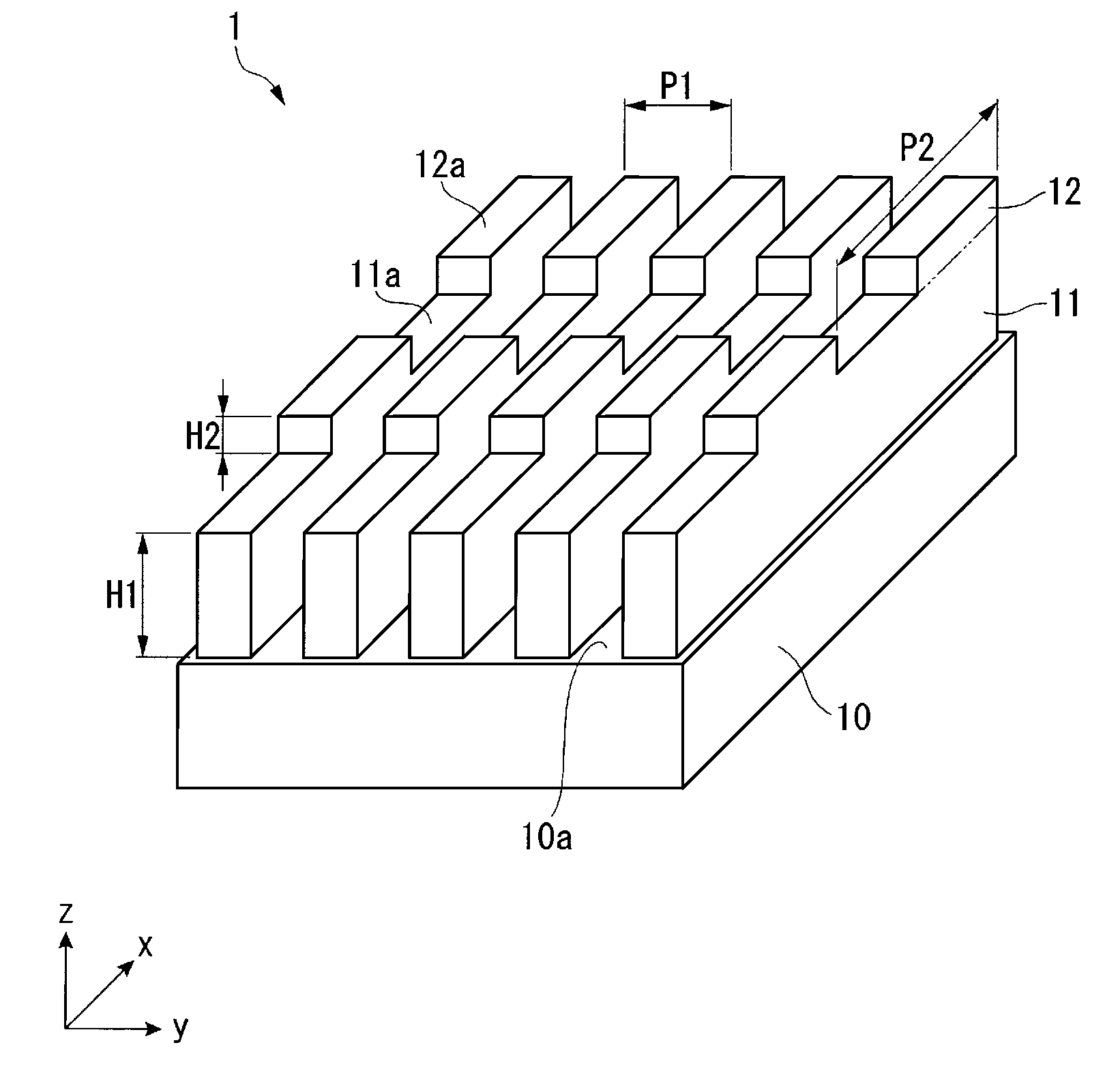
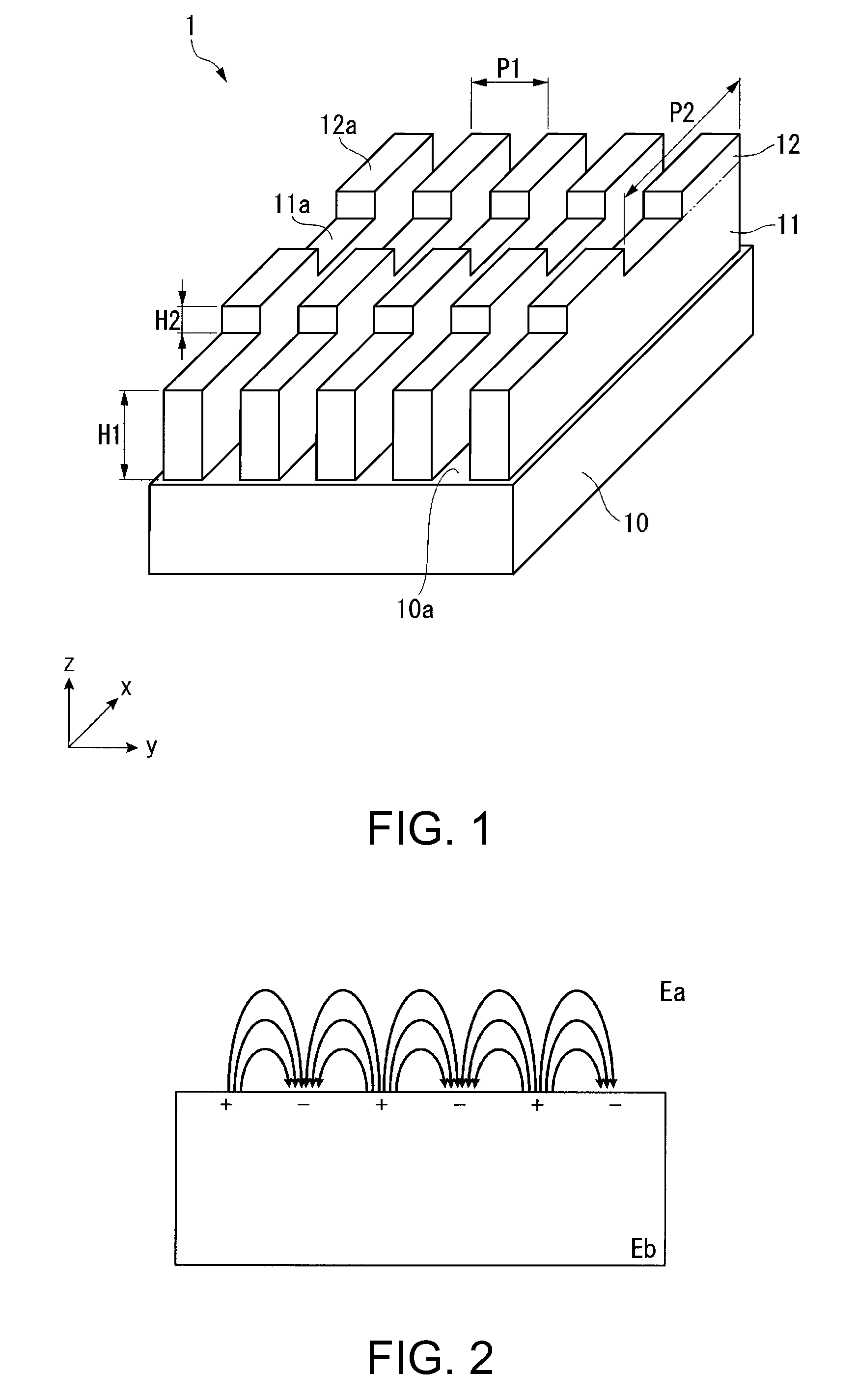
[0103]The inventors have performed an evaluation by a simulation analysis in order for confirming the effectiveness of the polarization element according to the embodiment of the invention. The simulation analysis has been performed using an electromagnetic field analysis by a finite difference time domain (FDTD) method.

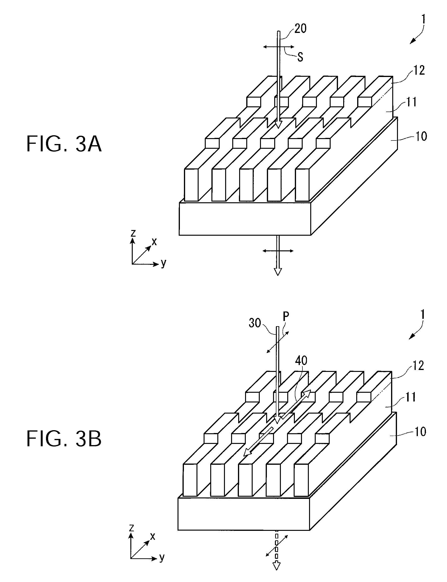
[0104]As the specific example, the polarization element (see FIG. 1) according to the present embodiment of the invention is used, and as a comparative example, a structure (what is obtained by eliminating the protruding sections from the polarization element shown in FIG. 1) with no resonant grating formed is used. The optical characteristics in which the specific example and the comparative example are compared are alight transmission rate (Tp) with respect to the TM light, a light transmission rate (Tc) with respect to the TE light, a reflectance (Rp) with respect to the TM light, and a reflectance (Rc) with respect to the TE light.

[0105]FIGS. 6A through 6C, and 7...


PUM


Abstract

A polarization element includes: a substrate; a plurality of thin metal wires provided to the substrate in a striped manner; and a plurality of protruding sections made of metal provided to each of the thin metal wires, and arranged in a longitudinal direction of the thin metal wire at a pitch shorter than a wavelength of incident light.

Description

BACKGROUND[0001]1. Technical Field[0002]The present invention relates to a polarization element and a projector.[0003]2. Related Art[0004]Recent years, wire grid polarization elements have been known as optical elements having a polarization separation function. The wire grid polarization elements are each obtained by forming nanoscale thin metal wires on a transparent substrate such as a glass substrate so as to line the substrate with the metal wires. The wire grid polarization elements have a characteristic of having a high polarization separation performance, and in addition, being superior in heat resistance to polarization elements made of organic materials since the wire grid polarization elements are made of inorganic materials. Therefore, use of wire grid polarization elements instead of polarization separation elements in the related art made of polymeric materials is considered in various optical systems. Specifically, the wire grid polarization elements are preferably us...

Claims


Application Information

Patent Timeline
IPC IPC(8): G02F1/1335G02B5/30
CPCG02B5/1861G02B5/3058G02B5/189
Inventor SAWAKI, DAISUKE
Owner SEIKO EPSON CORP
Why Eureka
Try Eureka