Optical device

a technology of optical devices and bragg gratings, applied in the field of optical devices, can solve the problems of reducing the mechanical bending flexibility of the device in a plane, changing the strain of the bragg grating, and changing the light interference condition, and achieve the effect of sensitivity of at least one first bragg grating to respond

Active Publication Date: 2011-05-19
ARKWRIGHT TECH PTY LTD
View PDF3 Cites 9 Cited by
  • Summary
  • Abstract
  • Description
  • Claims
  • Application Information

AI Technical Summary

Benefits of technology

[0045]At least some of the optical fibre portions may be bent at the sensing regions. For example, the at least one first and at least one second sensing region may be bent away from each other, and are typically curved, so that a convexly shaped area is defined between the at least one first and the at least one second optical fibre portions. Since the optical fibre portions are curved, the sensitivity of the at least one first Bragg grating to respond to a change in external force with a change in strain typically is increased.
[0046]In this embodiment the at least one s

Problems solved by technology

A change in an external pressure or temperature may cause a change in strain of the Bragg grating, which in turn causes a change in a light interference condition.
However, such opti

Method used


Image

  • Optical device
  • Optical device
  • Optical device

Examples


Embodiment Construction

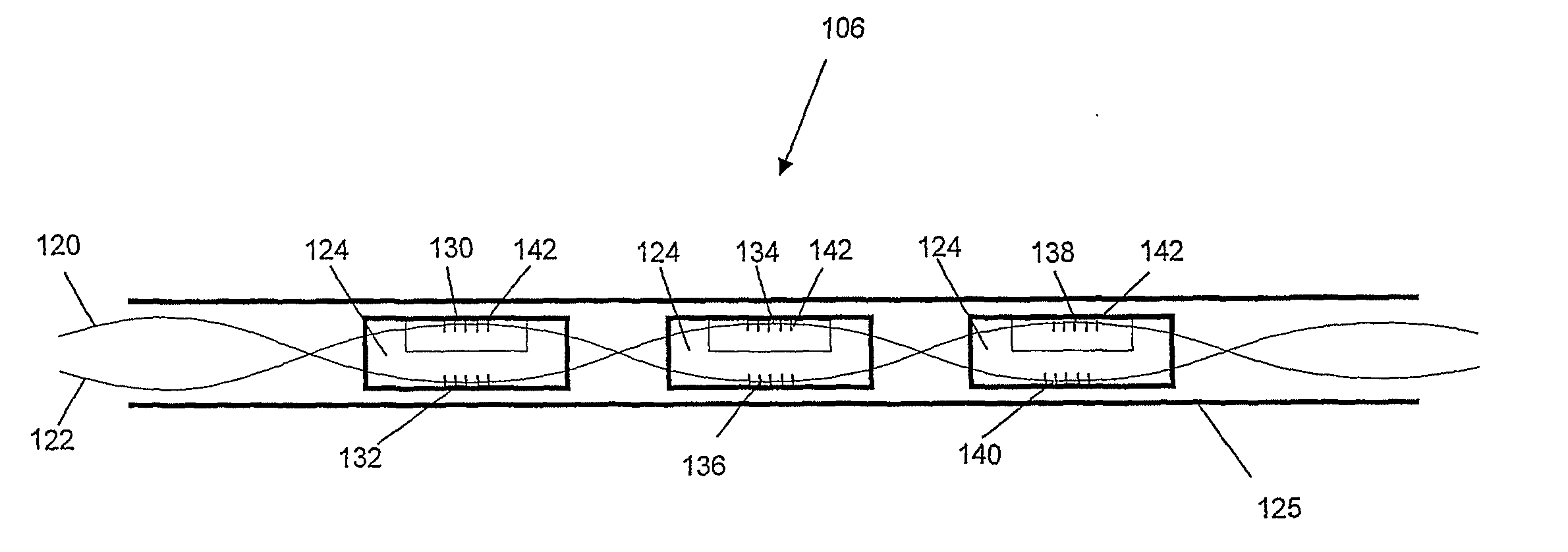
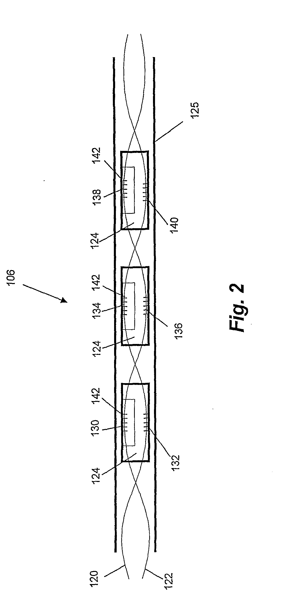
[0051]An optical device according to embodiments of the present invention is now described. In the described embodiment the optical device is arranged for pressure sensing. However, it is to be appreciated by a person skilled in the art that the device may alternatively be arranged for sensing any other properties, such as temperature or strain. Further, the device may be arranged for sensing any number of suitable properties, which may or may not be the same properties. In addition, the optical device may not be arranged for sensing a property.

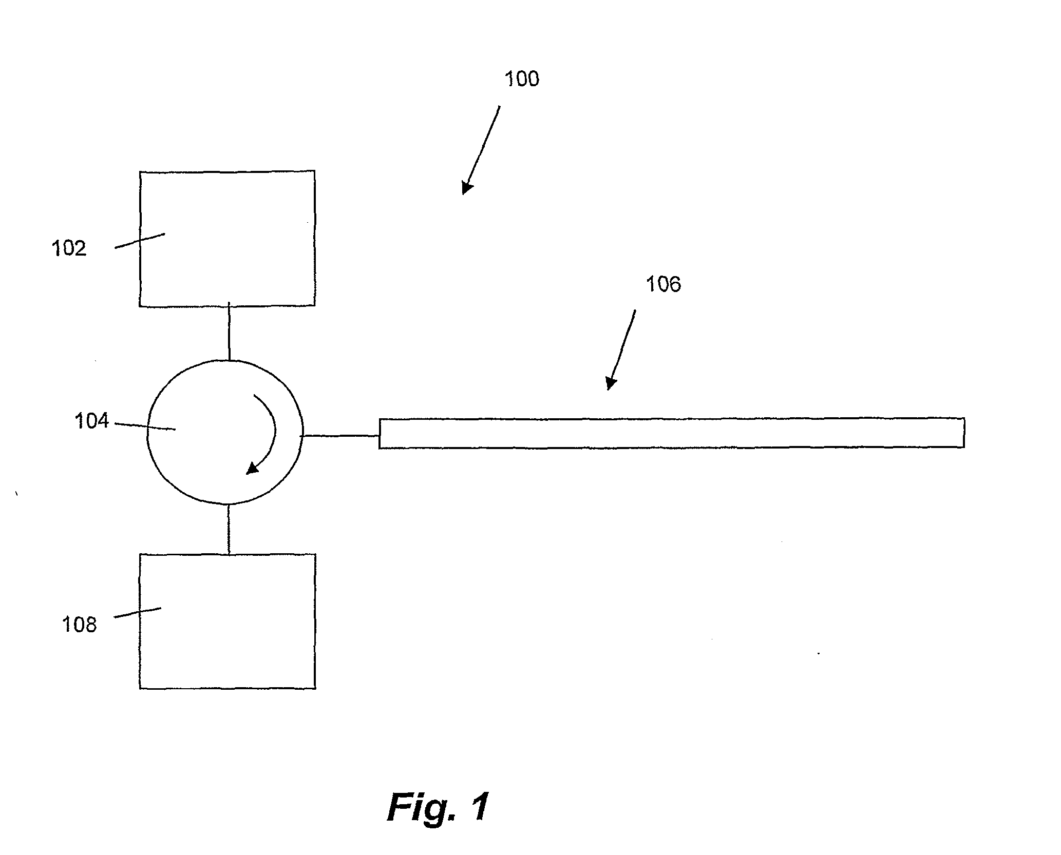
[0052]Referring initially to FIG. 1, a system for pressure sensing is now described. The system 100 comprises a light source 102 which in this embodiment is a broadband light source commonly referred to as a “white” light source even though the light that is emitted by the light source 102 may have any continuous wavelength range. The light is directed via optical circulator 104 to a device for pressure sensing 106. In a variation of this emb...


PUM


Abstract

The present disclosure provides an optical device comprising a first optical fibre portion having a first region and further regions between which the first region is positioned. The optical device also comprises a second optical fibre portion having a second region and further regions between which the second region is positioned. Further, the optical fibre comprises at least one member to which the first and second optical fibre portions are attached at the first and second regions. The first and second regions are positioned at opposite sides of an area defined between the first and second regions and spaced apart from each other by a first distance and wherein adjacent further regions are spaced apart by a second distance that is smaller than the first distance.

Description

FIELD OF THE INVENTION[0001]The present invention broadly relates to an optical device and relates specifically, though not exclusively, to an optical device for sensing a property.BACKGROUND OF THE INVENTION[0002]Optical devices are widely used for sensing different properties. Such optical devices may comprise optical fibres that have sensing regions in which a change in a property causes a change in an optical condition for guiding light in the optical fibres.[0003]For example, an optical device may be arranged for sensing changes in temperature, strain or pressure and may comprise a Bragg grating which has an optical response that depends on the strain of the Bragg grating. A change in an external pressure or temperature may cause a change in strain of the Bragg grating, which in turn causes a change in a light interference condition. Consequently, the change in external pressure or temperature can be detected by monitoring an optical response of the Bragg grating.[0004]The opti...

Claims


Application Information

Patent Timeline
IPC IPC(8): G02B6/34G02B6/38
CPCA61B5/01G01D5/35387A61B5/036A61B6/12A61B2562/0247A61B2562/0266A61B2562/0271G01D5/353G01L1/246G01L9/0077G02B6/2932G01L1/243G01L1/247G02B6/124G01D5/35316A61B5/02154
Inventor ARKWRIGHT, JOHN WILLIAMUNDERHILL, IANBLENMAN, NEIL
Owner ARKWRIGHT TECH PTY LTD
Why Eureka
Try Eureka