Cardiac ablation devices

a technology applied in the field of catheters and arteries, can solve the problems of difficult to ensure the proper placement of the catheter assembly, difficult to engage the tip of the ostium, and damage to delicate tissues within the pulmonary vein, so as to facilitate the threading of the catheter and facilitate the expansion of the structur

Inactive Publication Date: 2011-05-19
RECOR MEDICAL INC
View PDF103 Cites 16 Cited by
  • Summary
  • Abstract
  • Description
  • Claims
  • Application Information

AI Technical Summary

Benefits of technology

[0013]A method according to a related aspect of the invention includes the step of providing an ablation device in a chamber of the heart of a mammalian subject, such that the device is in an operative configuration with a distal side of the device facing toward a region of the cardiac structure to be ablated, and, while the ablation device is in its operative configuration, injecting a contrast medium into the chamber on the distal side of the ablation device. The method most desirably further includes obtaining one or more images depicting the contrast medium in at least a portion of the cardiac structure as, for example, by x-ray or fluoroscopic imaging. Methods according to this aspect of the invention allow the physician to confirm placement of the device while the device is in its operative condition as, for example, while a balloon or other expansible structure is in its expanded state. Most preferably, the methods according to this aspect of the invention are performed without introducing a separate catheter to carry the contrast medium, as by using the continuous passageway discussed above in connection with the apparatus. The methods according to this aspect of the invention may further include the step of adjusting the position of the ablation device, based in part or entirely on the relationship between the ablation device and the cardiac structure observed in the imaging step. These methods allow the physician to position the device during the procedure, without relying on a predetermined mechanical relationship between the device and the cardiac structure.
[0014]Apparatus according to a further embodiment of the invention includes a catheter and an ultrasonic device having a forward-to-rearward axis. The ultrasonic device is arranged to emit ultrasonic waves so that the emitted ultrasonic waves are directed into at least a portion of a ring-like region surrounding the forward-to-rearward axis. The ablation device is mounted to the catheter. Apparatus according to this aspect of the invention includes a steering system adapted to selectively vary the disposition of the ablation device and, in particular, the disposition of the forward-to-rearward axis of the ablation device relative to the heart of the subject, while the ultrasonic ablation device is disposed in a chamber of the heart of the subject. Here again, the ultrasonic ablation device most preferably includes an expansible structure such as a balloon structure having a collapsed, inoperative state and an expanded state. The steering system preferably is operative to selectively vary the disposition of the ablation device while the expansible structure is in its expanded state as, for example, while a balloon-based expanded structure is in an inflated condition. Most preferably, the steering system is arranged to selectively vary the disposition of the ultrasonic ablation device independently of engagement between the cardiac structure and any element of the apparatus distal to the ultrasonic ablation device. Most preferably, the catheter has a bendable section located proximally or rearwardly of the forward end of the ablation device, and the steering system is arranged to selectively bend this bendable section of the catheter under the control of the physician. In a particularly preferred arrangement, the expansible structure includes an internal reinforcing structure having a distal end linked to the expansible structure adjacent the forward end of the expansible structure, and having a proximal end mechanically linked to the expansible structure adjacent the rearward end thereof. The reinforcing structure may include an ultrasonic emitter assembly, as well as an extensible structure. Preferably, the reinforcing structure becomes relatively flexible when the expansible structure is in a collapsed condition and becomes more rigid when the expansible structure is in its expanded condition. As further discussed below, this arrangement allows the reinforcing structure to maintain the shape of the expansible structure in its expanded or inflated condition, but facilitates threading of the device through the body to the heart.
[0015]The steering system most desirably includes at least one pull wire mechanically connected to the reinforcing structure, typically adjacent the proximal end thereof. As further discussed below, steering by pulling on the internal reinforcing structure within the expansible structure tends to bend the catheter in such a way that the expansible structure turns about a pivot axis relatively close to the forward end of the expansible structure. This makes it easier to maneuver the expanded structure within the confines of a heart chamber.
[0017]Desirably, at least one of the dispositions of the ablation device is a so-called “normal” disposition in which the forward-to-rearward axis of the device lies approximately perpendicular to a wall of the heart with at least a major portion of the ring-like ablation region disposed within or in close proximity to the wall of the heart. Ablation in this disposition forms a lesion in the form of at least a substantial portion of a loop. Alternatively or additionally, at least one of the dispositions may be a canted disposition in which the forward-to-rearward axis of the device lies at a substantially non-perpendicular angle to the wall of the heart, so that only a minor portion of the ring-like region is disposed within or in close proximity to the wall of the heart. Ablation in this disposition forms a lesion in the form of only a small portion of a loop, approximating a linear lesion. Thus, the same tool can be used to form both loop-like lesions and substantially linear lesions. Most desirably, the ablation device is arranged to focus the ultrasonic waves into the ring-like ablation region, so that the ultrasonic waves have intensity which increases in the direction of propagation of the energy from the device to the ablation region and decreases in the same direction, beyond the ablation region. Typically, the ultrasonic waves are directed indiscriminately into the entire ablation region. In the normal disposition, all or almost all of this energy performs the desirable function of ablating the loop-like lesion. However, in the canted disposition, only a portion of the ablation region is disposed where ablation is desired. Other portions of the ablation region typically are disposed remote from a heart wall to be ablated. However, ultrasonic waves directed into those remote portions of the ablation region will pass through the ablation region and will dissipate, typically without damaging other structures.

Problems solved by technology

Also, two or more pulmonary veins may join one another close to a common opening or ostium or may be enlarged or shaped so that it is difficult to engage the tip in the ostium.
Moreover, even where the patient has the desired, nominal anatomy, it has been difficult to confirm proper placement of the balloon assembly.
The delicate tissues within the pulmonary vein can be damaged by forcibly engaging structures with these tissues and by moving the engaged structures while the structures are forcibly engaged with the tissues.
Such a catheter may be provided as a separate device which must be separately introduced into the heart, thus complicating and prolonging the procedure.
Although this approach theoretically simplifies the task of positioning the needed devices within the heart, in fact, it substantially complicates the construction of the device and also complicates the tasks of positioning each individual device.

Method used


Image

  • Cardiac ablation devices
  • Cardiac ablation devices
  • Cardiac ablation devices

Examples


Embodiment Construction

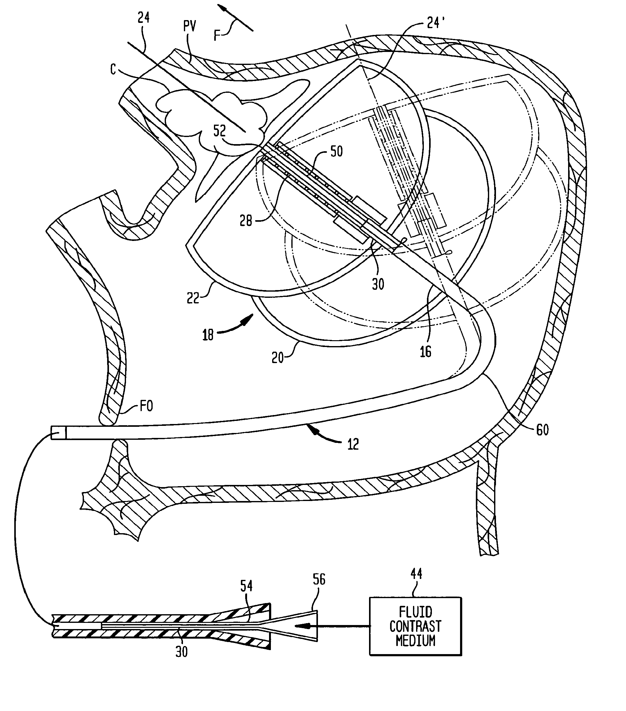
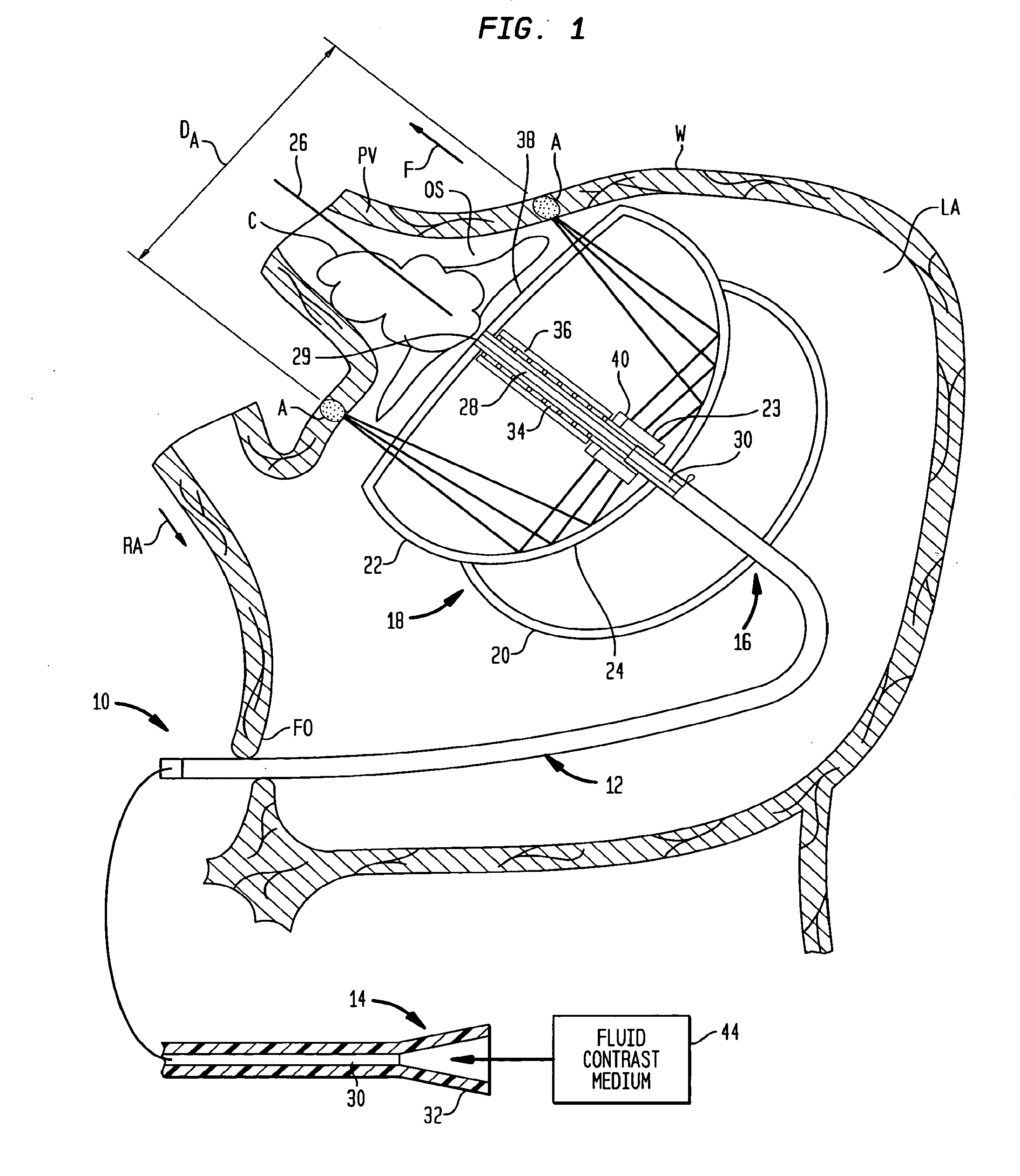
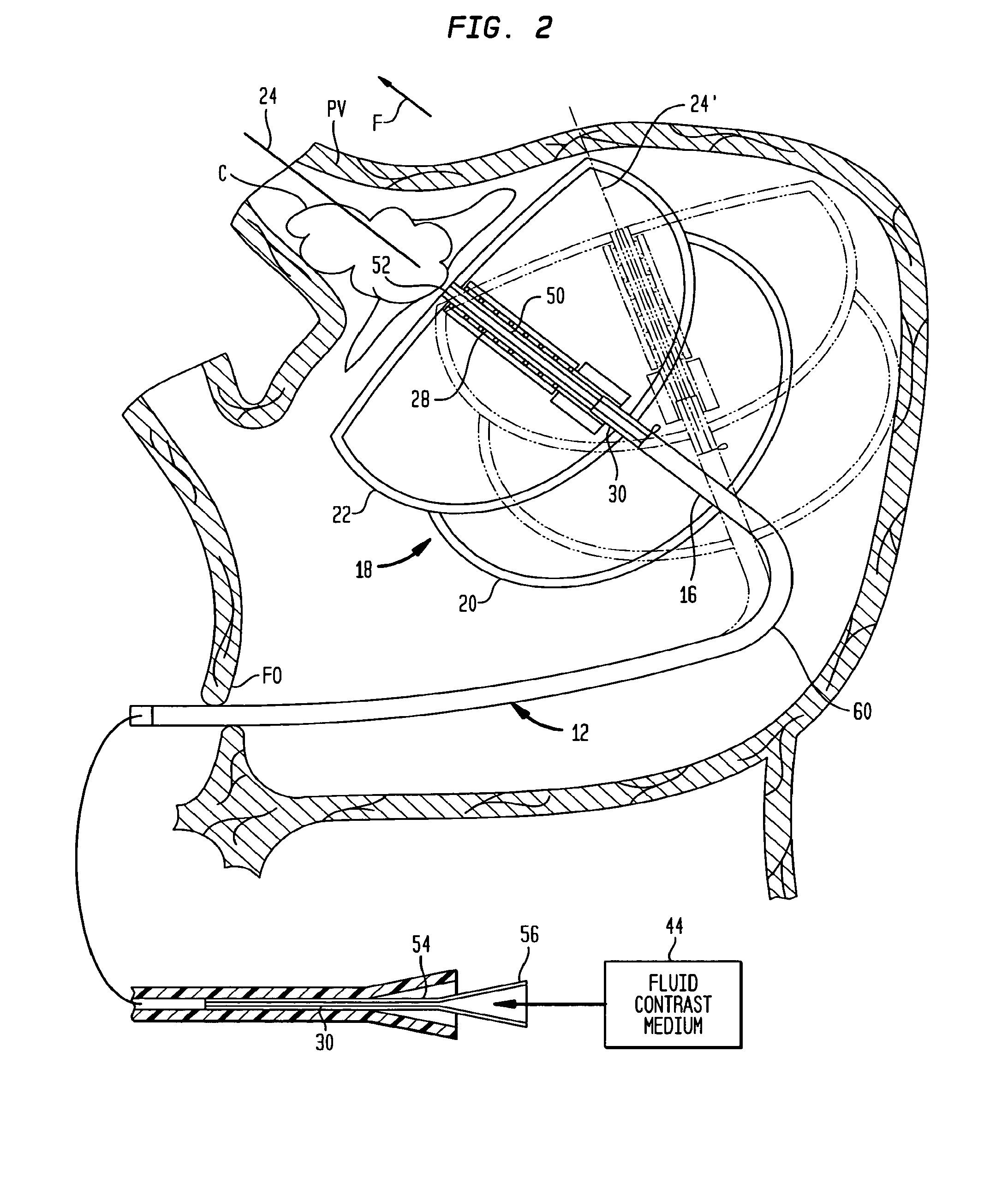
[0057]As seen in FIG. 1, apparatus according to one embodiment of the invention includes an insertable structure 10 incorporating an elongated catheter 12 having a proximal end 14, which remains outside of the body, and a distal end 16 adapted for insertion into the body of the subject. As used in this disclosure with reference to structures which are advanced into the body of a subject, the “distal” end of such a structure should be taken as the end which is inserted first into the body and which penetrates to the greatest depth within the body, whereas the proximal end is the end of the structure opposite to the distal end. The insertable structure 10 also includes an ablation unit 18 mounted to the catheter adjacent distal end 16. Ablation unit 18 incorporates a reflector balloon 20 and a structural balloon 22 having a common wall 24. Reflector balloon 20 is linked to an inflation lumen (not shown) in catheter 10, which extends to the proximal end of the catheter and which is con...


PUM


Abstract

A cardiac ablation device treats atrial fibrillation by directing and focusing ultrasonic waves into a ring-like ablation region (A). The device desirably is steerable and can be moved between a normal disposition, in which the ablation region lies parallel to the wall of the heart for ablating a loop-like lesion, and a canted disposition, in which the ring-like focal region is tilted relative to the wall of the heart, to ablate only a short, substantially linear lesion. The ablation device desirably includes a balloon reflector structure (18, 1310) and an ultrasonic emitter assembly (23, 1326), and can be steered and positioned without reference to engagement between the device and the pulmonary vein or ostium. A contrast medium (C) can be injected through the ablation device to facilitate imaging, so that the device can be positioned based on observation of the images.

Description

CROSS-REFERENCE TO RELATED APPLICATIONS[0001]The present application is a continuation of U.S. patent application Ser. No. 10 / 783,310, filed Feb. 20, 2004, now U.S. Pat. No. 7,837,676, which claims benefit of U.S. Provisional Patent Application Ser. No. 60 / 448,804, filed Feb. 20, 2003, the entire contents of both of which are hereby incorporated by reference herein.BACKGROUND OF THE INVENTION[0002]The present invention relates to ablation apparatus and methods and to steerable devices, including those used in cardiac ablation[0003]Contraction or “beating” of the heart is controlled by electrical impulses generated at nodes within the heart and transmitted along conductive pathways extending within the wall of the heart. Certain diseases of the heart known as cardiac arrhythmias involve abnormal generation or conduction of the electrical impulses. One such arrhythmia is atrial fibrillation or “AF.” Certain cardiac arrhythmias can be treated by deliberately damaging the tissue along a...

Claims


Application Information

Patent Timeline
Patent Type & Authority Applications(United States)
IPC IPC(8): A61N7/00A61B17/00A61B17/22
CPCA61B17/22004A61B17/22012A61B17/2202A61B17/2251A61B2017/00991A61B2017/22027A61B2017/22054A61B2017/22061A61B2017/00243
Inventor SINELNIKOV, YEGORZOU, YONGWARNKING, REINHARDSAVAGE, JAMESPACHECO, ROBERT C.MERINO, JAIMELOPATH, PATRICK DAVIDHOTMER, JOHNFJIELD, TODD
Owner RECOR MEDICAL INC
Why Eureka
Try Eureka