Self-shielded gradient coil

a gradient coil and self-shielde technology, applied in the field of magnetic resonance imaging systems and methods, to achieve the effect of reducing eddy currents

Active Publication Date: 2011-05-26
VIEWRAY TECH
View PDF16 Cites 75 Cited by
  • Summary
  • Abstract
  • Description
  • Claims
  • Application Information

AI Technical Summary

Benefits of technology

[0008]Gradient coil assemblies and methods for their manufacture and use within horizontal MRIs are disclosed. Some embodiments may be used in conjunction with an open MRI and an instrument placed within its gap. Embodiments of the gradient coil assemblies disclosed herein may include primary gr

Problems solved by technology

However, problems exist with this placement because of interference from various magnetic fields associated

Method used


Image

  • Self-shielded gradient coil
  • Self-shielded gradient coil
  • Self-shielded gradient coil

Examples


Embodiment Construction

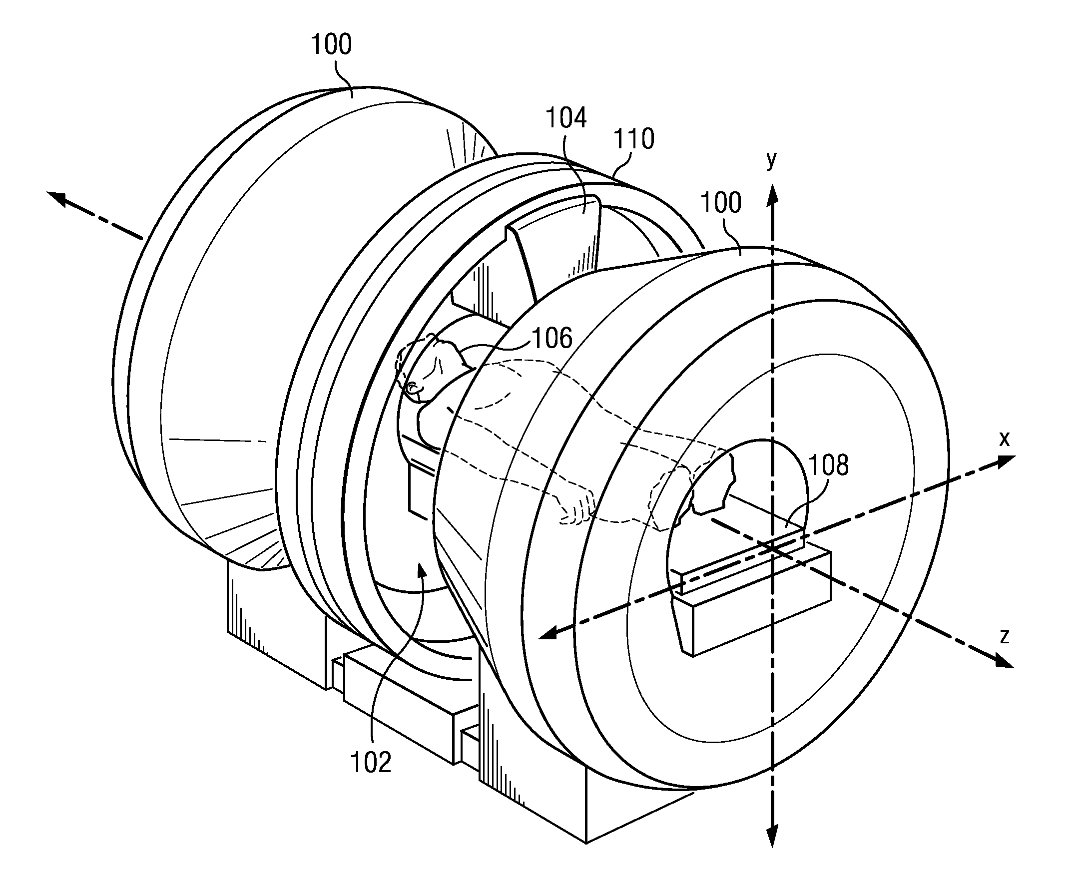
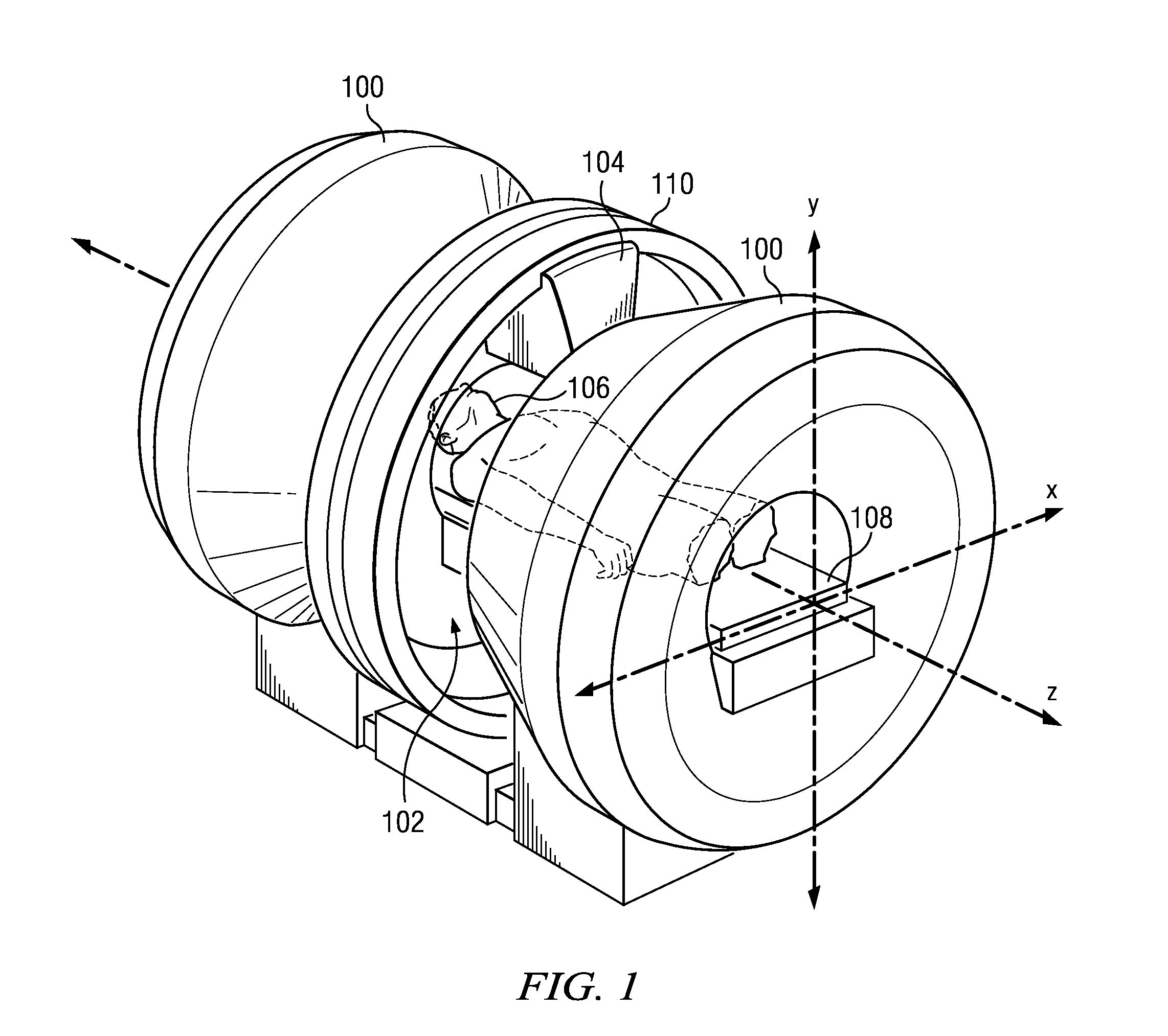
[0043]The gradient coil assembly of the present disclosure may be used with any type of horizontal magnetic resonance imaging (MRI) system. It is particularly well suited for use with a split solenoid or horizontal “open” MRI that includes a gap between two horizontal MRI magnet halves. The gradient coil assemblies disclosed herein are further well suited for use with a horizontal open MRI that is used with an additional medical instrument being operated within its gap. FIG. 1 depicts such an arrangement with a horizontal open MRI 100 having a gap region 102. An instrument 104 is mounted in the gap region 102 on a gantry 110. Also depicted are a patient 106 and patient couch 108. In some embodiments, the gantry 110 can be used to reposition the instrument 104 about the patient 106 (i.e., about the Z-axis shown in FIG. 1).

[0044]The embodiment of FIG. 1 can include elements of a system of the assignee of the current application, ViewRay, Inc., described, in part, in U.S. Patent Applic...


PUM


Abstract

Gradient coil assemblies for horizontal magnetic resonance imaging systems (MRIs) and methods of their manufacture. Some embodiments may be used with open MRIs and can be used with an instrument placed in the gap of the MRI. In general, concentrations of conductors or radially oriented conductors may be moved away from the gap of the MRI so as to reduce eddy currents that may be induced in any instrument placed within the gap. Systems for directly cooling primary gradient and shield coils may be utilized and various coil supporting structures may be used to assist in coil alignment or to facilitate use of an instrument in the MRI gap.

Description

RELATED APPLICATION[0001]This application claims the benefit of U.S. Provisional Application No. 61 / 263,280, filed Nov. 20, 2009, titled “Self-Shielded Split Gradient Coil,” which is hereby incorporated by reference.BACKGROUND[0002]1. Technical Field[0003]The present application relates to systems and methods for magnetic resonance imaging (“MRI”) and particularly to gradient coil assemblies and methods for their manufacture and use with magnetic resonance imaging systems.[0004]2. Related Art[0005]Magnetic resonance imaging, or nuclear magnetic resonance imaging, is primarily a medical imaging technique used most commonly in radiology to visualize the internal structure and function of the body. MRI is described, for example, by E. MARK HAACKE ET AL., MAGNETIC RESONANCE IMAGING: PHYSICAL PRINCIPLES AND SEQUENCE DESIGN (Wiley-Liss 1999), which is hereby incorporated by reference. The present disclosure relates to the magnetic resonance arts and specifically to horizontal (solenoid ma...

Claims


Application Information

Patent Timeline
IPC IPC(8): G01R33/44
CPCG01R33/385G01R33/3856G01R33/4215G01R33/3858G01R33/4808A61N2005/1055G01R33/3806
Inventor SHVARTSMAN, SHMARYU M.DEMEESTER, GORDON D.PATRICK, JOHN L.DEMPSEY, JAMES F.
Owner VIEWRAY TECH
Why Eureka
Try Eureka