Touch display apparatus and backlight module

a technology of backlight module and display apparatus, which is applied in the field of display and light source modules, can solve the problems of limiting the applicability range, affecting the user's experience, and affecting the user's experience, and achieves the effect of increasing the transmission distance of invisible light beams and small profiles

Inactive Publication Date: 2011-05-26
CORETRONIC
View PDF13 Cites 25 Cited by
  • Summary
  • Abstract
  • Description
  • Claims
  • Application Information

AI Technical Summary

Benefits of technology

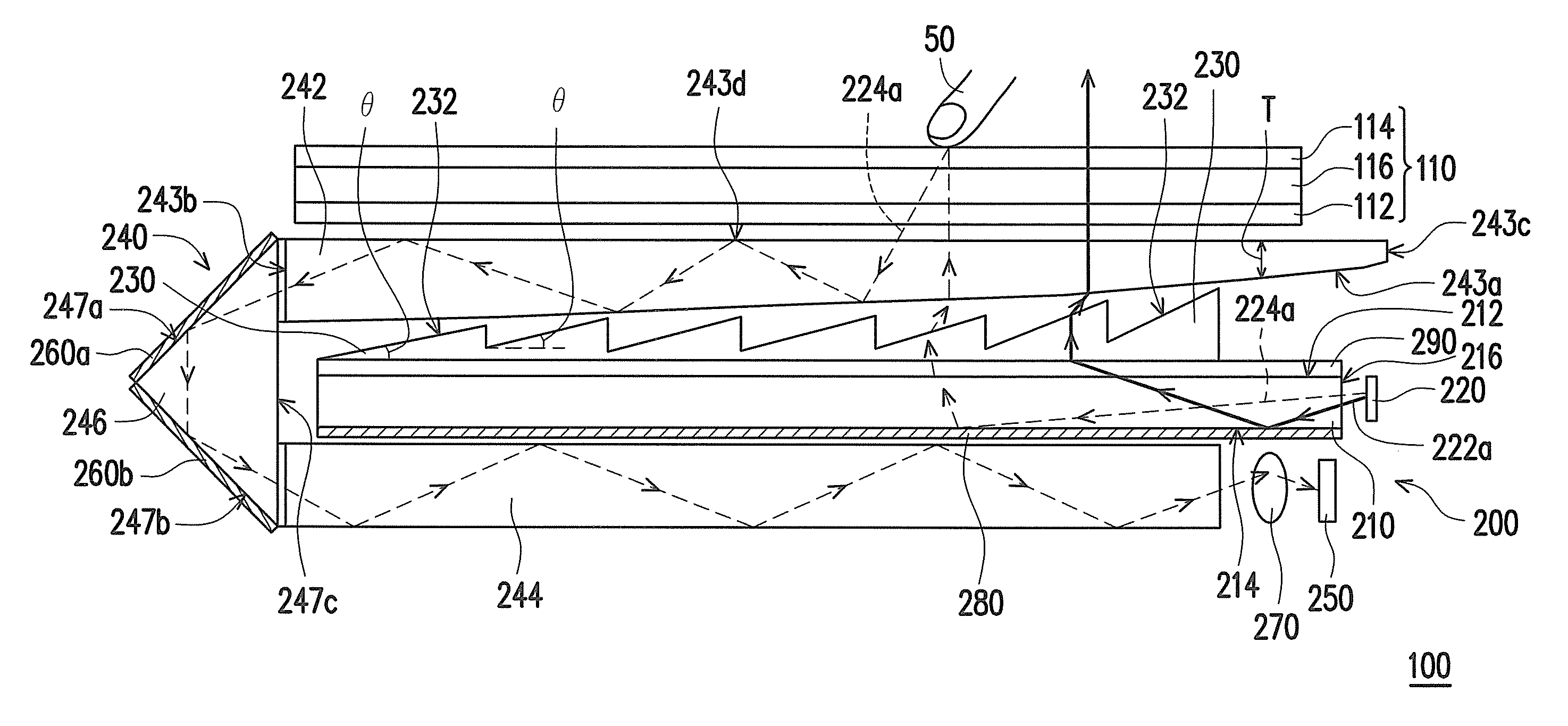
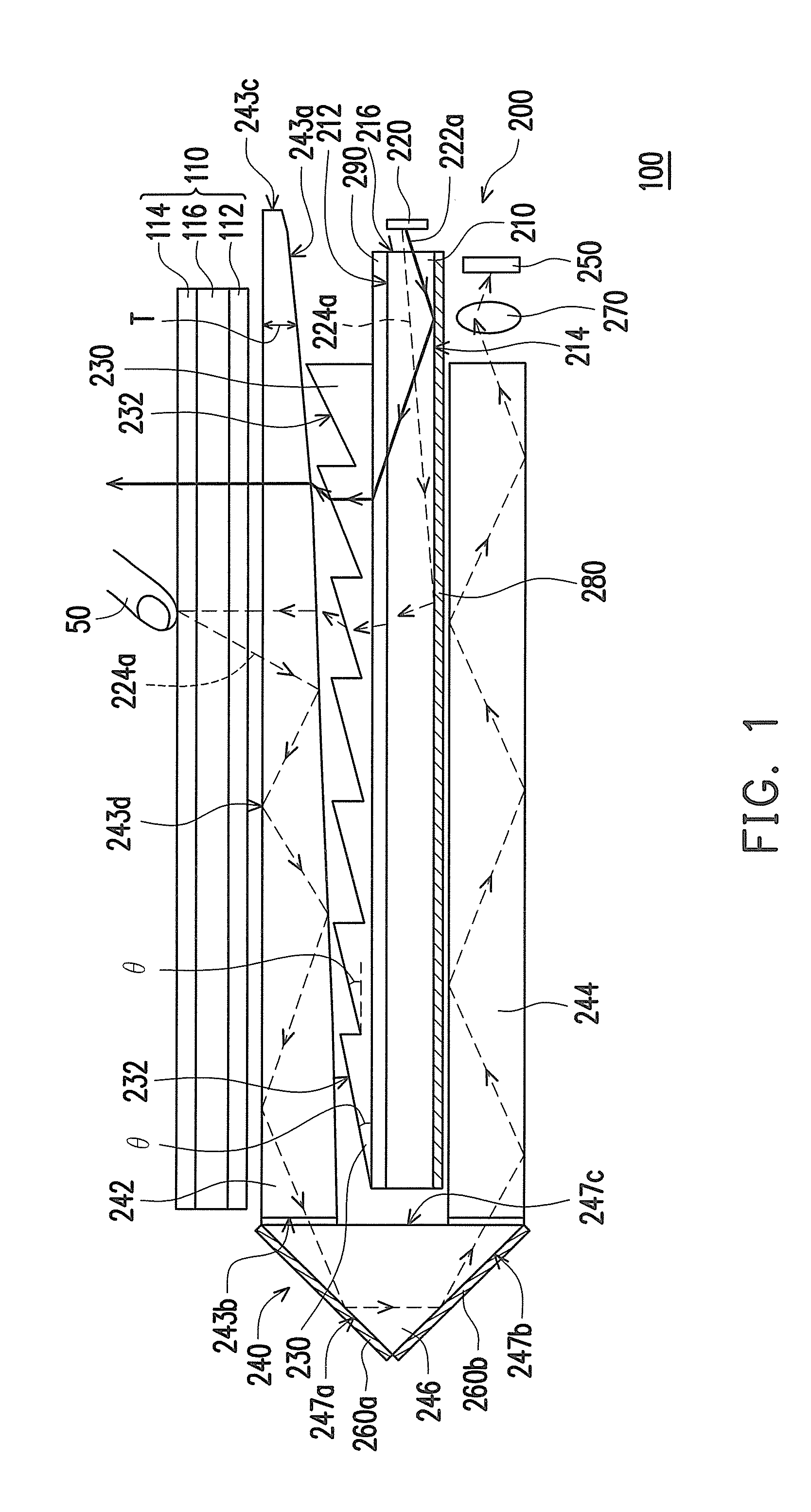
[0016]In summary, the embodiment or the embodiments of the invention may have at least one of the following advantages. According to embodiments of the invention, the touch display apparatus and the backlight module adopt the image transmission unit so that the invisible light beam reflected by the touch object is transmitted to the image detector. Consequently, a transmission distance of the invisible light beam may be increased, while not excessively adding to the size of the touch display apparatus or the size of the backlight module. Therefore, the touch display apparatus and the backlight module according to embodiments of the invention may achieve a small profile. Moreover, according to embodiments of the invention, the touch display apparatus and the backlight module adapt the wedge portion of the image transmission unit to receive the invisible light beam from the touch object. Therefore, if a plurality of touch objects simultaneously approach or touch the display panel and the wedge portion, the images of the touch objects may be formed at different locations on the optical detector, without a blockage issue. Accordingly, the touch display apparatus and the backlight module according to embodiments of the invention may achieve a multi-touch function.

Problems solved by technology

With the advancement of optoelectronic technologies, a user may no longer be satisfied with controlling a computer and objects on screen through a mouse.
However, since multiple detection cameras, as well as the projector providing the set of projection images, and the infrared light sources are placed inside the table, the entire device is overly bulky, therefore restricting the range of applicability.
Even if the components under the table are packaged together, the user, when seated, may not extend his legs because the space near the knees is limited.
However, this method of determining the finger touch locations by calculating the finger position obstructing the infrared light is not suitable for multi-touch or touch input from multiple users.

Method used


Image

  • Touch display apparatus and backlight module
  • Touch display apparatus and backlight module
  • Touch display apparatus and backlight module

Examples


Embodiment Construction

[0022]In the following detailed description of the preferred embodiments, reference is made to the accompanying drawings which form a part hereof, and in which are shown by way of illustration specific embodiments in which the invention may be practiced. In this regard, directional terminology, such as “top,”“bottom,”“front,”“back,” etc., is used with reference to the orientation of the Figure(s) being described. The components of the invention can be positioned in a number of different orientations. As such, the directional terminology is used for purposes of illustration and is in no way limiting. On the other hand, the drawings are only schematic and the sizes of components may be exaggerated for clarity. It is to be understood that other embodiments may be utilized and structural changes may be made without departing from the scope of the invention. Also, it is to be understood that the phraseology and terminology used herein are for the purpose of description and should not be ...


PUM


Abstract

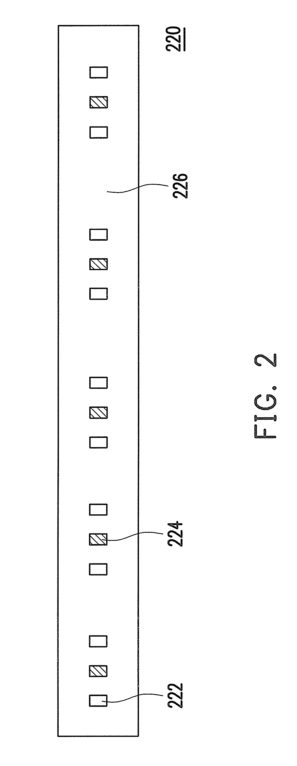
A touch display apparatus including a light guide plate, a light emitting module, a display panel, a plurality of prism structures, an image transmission unit, and an image detector is provided. The light guide plate has a first surface, a second surface opposite to the first surface, and a light incident surface connecting the first surface and the second surface. The light emitting module includes at least one visible light source and at least one invisible light source. The prism structures are disposed between the first surface and the display panel. The image transmission unit includes a wedge portion and a light guide portion. The wedge portion is disposed between the prism structures and the display panel. The image detector is disposed beside the light guide portion for receiving the invisible light beam from the light guide portion. A backlight module is also provided.

Description

CROSS-REFERENCE TO RELATED APPLICATION[0001]This application claims the priority benefit of Taiwan Patent Application serial No. 98139809, filed on Nov. 23, 2009. The entirety of the above-mentioned patent application is hereby incorporated by reference herein and made a part of this specification.BACKGROUND OF THE INVENTION[0002]1. Field of the Invention[0003]The invention generally relates to a display and a light source module, and more particularly to a touch display apparatus and a backlight module.[0004]2. Description of Related Art[0005]With the advancement of optoelectronic technologies, a user may no longer be satisfied with controlling a computer and objects on screen through a mouse. Accordingly, more user-friendly interface techniques than the mouse have been gradually developed. In the intuitive techniques, a finger-controlled touch interface commanding the computer approximates the natural experiences of human users.[0006]In conventional techniques, a plurality of meth...

Claims


Application Information

Patent Timeline
Patent Type & Authority Applications(United States)
IPC IPC(8): G06F3/042G06F3/041F21V7/22
CPCG02B6/0046G02B6/0053G06F3/042G02B6/0076G02B6/0068
Inventor TSAI, HAN-WENCHUANG, FU-MING
Owner CORETRONIC
Why Eureka
Try Eureka