Method and System for Enhancing Contrast of Spatially-Localized Phenomena in Mammography Image

a spatially localized phenomenon and contrast enhancement technology, applied in image enhancement, image analysis, instruments, etc., can solve the problem of difficult accurate delineation of microcalcifications in mammogram images, and achieve the effect of enhancing contrast and enhancing contras

Active Publication Date: 2011-05-26
AGFA NV
View PDF3 Cites 4 Cited by
  • Summary
  • Abstract
  • Description
  • Claims
  • Application Information

AI Technical Summary

Benefits of technology

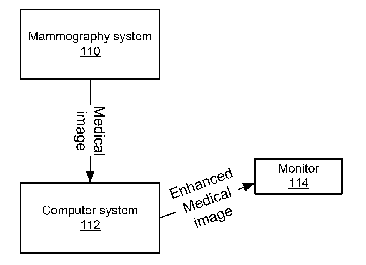
[0016]The above-mentioned advantageous effects are realized by a computer-implemented method of enhancing the contrast of spatially localized phenomena in a medical image. The method comprises applying a multi-scale decomposition to a digital signal representation of the image thereby generating a number of detail images at different scales. The detail signals that pertain to the spatially localized phenomena having a first common polarity are modified at at least one of the scales and detail signals pertaining to the localized phenomena having a second common polarity are left un-changed.
[0017]In embodiments, modification is preceded by a thresholding step applied to the detail signals of common polarity. Also, the spatial extent of the region to which the modification is applied is limited to pixels within a neighbourhood of fixed shape surrounding the position of said spatially localized phenomena.
[0018]In some cases, the spatial extent of the region to which the modification is applied is determined by applying connected component analysis at said position(s). In other cases, the spatial extent of the region to which the modificati...

Problems solved by technology

An accurate delineation of microcalcifications in a mammogram image is difficult, especially in a mammogram generate...

Method used


Image

  • Method and System for Enhancing Contrast of Spatially-Localized Phenomena in Mammography Image
  • Method and System for Enhancing Contrast of Spatially-Localized Phenomena in Mammography Image
  • Method and System for Enhancing Contrast of Spatially-Localized Phenomena in Mammography Image

Examples


first embodiment

[0057]In a first embodiment the spatial extent has a fixed shape, such as a circle or rectangle, that roughly defines the region in which the detail signals, in this example the negative detail signals, must be enhanced.

second embodiment

[0058]In a second embodiment the spatial extent is determined at subsequent scales by applying a connected component analysis at the given coordinates of the spatially-localized phenomena. As criterion in the connected component analysis the sign of the detail signals is used.

third embodiment

[0059]In a third embodiment the spatial extent is determined by applying a region growing method whereby the given coordinates of the spatially-localized phenomena are used as seed points.

[0060]Another embodiment is to apply a segmentation method to the grayscale image at a certain resolution e.g. the watershed algorithm to delineate the microcalcifications around the given coordinates. The result is a binary mask that is extended using morphologically filtering (e.g. dilation filter) to enclose the microcalcifications in the image. This binary mask is interpolated or reduced to match the resolution of the detail signals in the multiscale decomposition. Negative detail signals indicated by the binary mask are enhanced.

[0061]The amount of enhancement can be fixed or can depend on local characteristics of the spatially-localized phenomena and its surrounding, as well in the grey value representation as in the multiscale representation.

[0062]There are different ways to locally modify t...


PUM


Abstract

In a method to enhance the contrast of spatially-localized phenomena in an image such as microcalcifications in a mammogram, a multi-scale decomposition is applied to a digital signal representation of the image thereby generating a number of detail images at different scales, the detail signals pertaining to the spatially-localized phenomena having a common polarity (either negative or positive) being modified at at least one scale.

Description

RELATED APPLICATIONS[0001]This application claims priority to European Patent Application No. 09014653.1. filed on Nov. 25, 2009, and claims the benefit under 35 USC 119(e) of U.S. Provisional Application No. 61 / 264,364, filed on Nov. 25, 2009, both of which are incorporated herein by reference in their entirety.BACKGROUND OF THE INVENTION[0002]Computer-aided detection and enhancement of microcalcifications in mammogram images is described by Gürcan et. al. in “Automated Detection and Enhancement of Microcalcifications in Mammograms Using Nonlinear Subband Decomposition,” Icassp, vol. 4, pp. 3069, 1997 IEEE International Conference on Acoustics, Speech, and Signal Processing (ICASSP'97)-Volume 4, 1997.[0003]Also in US patent application 2005 / 0135695 a similar approach is described.[0004]The general idea of the described method is a 3-step process to create an enhanced mammogram image: 1. detection of microcalcifications in the image, 2. segmentation of the microcalcifications in the...

Claims


Application Information

Patent Timeline
IPC IPC(8): G06K9/36
CPCG06T5/008G06T5/40G06T7/0081G06T2207/30068G06T2207/10081G06T2207/20016G06T2207/20152G06T7/0091G06T7/11G06T7/155
Inventor BERTENS, TOMVUYLSTEKE, PIETERBEHIELS, GERT
Owner AGFA NV
Why Eureka
Try Eureka