
Image processing apparatus, control method for the same, program

Inactive Publication Date: 2011-05-26
CANON KK
View PDF4 Cites 26 Cited by
  • Summary
  • Abstract
  • Description
  • Claims
  • Application Information

AI Technical Summary

Benefits of technology

[0008]The present invention enables realization of an image processing apparatus, a control method for the same, and a program that reduce the processing time taken to encode image data that has been divided into blocks, as well as suppresses a reduction in image quality.

Problems solved by technology

However, depending on the image, the lossless variable length method requires a very large amount of interpolation information in order to perform image compression.
However, with the variable length encoding method in the above-described conventional technology, the total encoded data amount cannot be known without actually performing encoding processing.
This processing is repeated until the memory capacity is not exceeded, and therefore is very time-consuming.
However, if the blocks into which the image data has been divided are compressed in order, image quality will degrade and an unclear image will be obtained if, for example, a large number of thin lines or characters are included in the image blocks toward the end.

Method used


Image

  • Image processing apparatus, control method for the same, program
  • Image processing apparatus, control method for the same, program
  • Image processing apparatus, control method for the same, program

Examples


embodiment 1

[0031]Configuration of Image Processing Apparatus

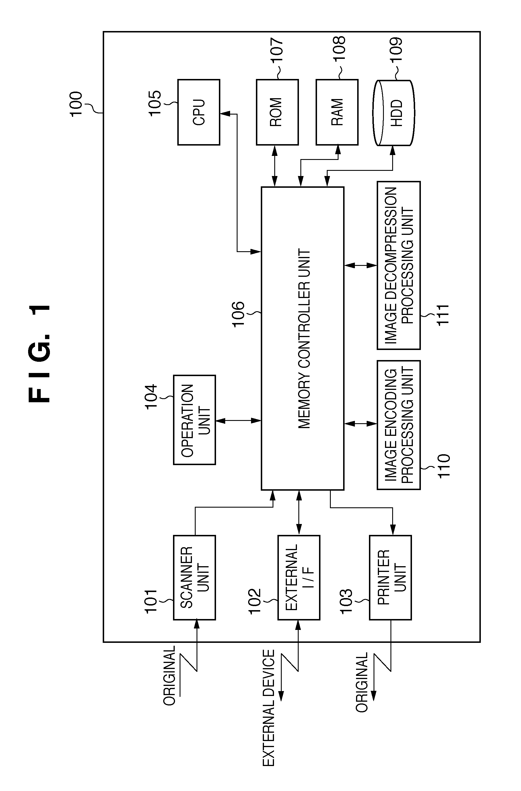
[0032]Below is a description of Embodiment 1 with reference to FIGS. 1 to 12. First, a description of the configuration of an image processing apparatus according to the present embodiment is given with reference to FIG. 1. The image processing apparatus according to the present embodiment is described taking the example of a multi-function peripheral (MFP). An MFP 100 is an image processing apparatus including a plurality of functions such as a copy function for printing job data that has been output from a scanner and stored in a memory, and a print function for printing job data that has been output from an external apparatus such as a computer and stored in a memory. The MFP 100 can be a full-color device or a monochrome device, and the basic configuration of a full-color device is often the same as that of a monochrome device, with the exception of color processing, internal data, and the like. The following description therefore...

embodiment 2

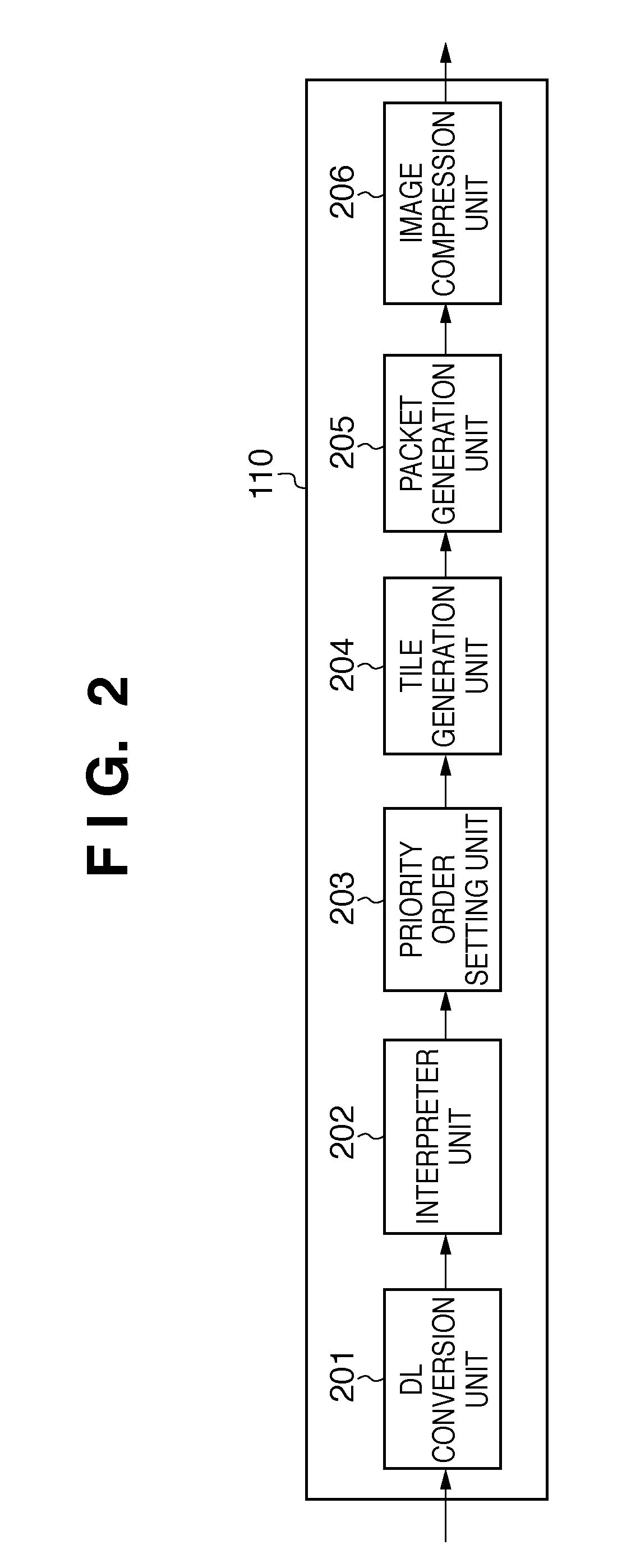
[0061]Next is a description of Embodiment 2 with reference to FIGS. 13 to 15. A feature of the present embodiment is that if the target of compression is an image having a high amount of change in image pixel values, such as when a large number of characters exist in tile images, the compression rate is raised in order to compress the image so as to fall within a target memory capacity. Note that the following description focuses mainly on aspects of the configuration and technology that are different from Embodiment 1. In the present embodiment, the interpreter unit 202 creates a Q table ID list that is used for selecting the quantization table to be used by the image compression unit 206.

[0062]First is a description of an example of a tile image to which the processing of the present embodiment is applied with reference to FIG. 13. The tile image shown in FIG. 13 has 0, 0, 5, 9, 9, 5, 9, 8, 0, and 0 edges in lines 0 to 9 respectively, and the total number of edges in the lines is ...

embodiment 3

[0066]Below is a description of Embodiment 3 with reference to FIGS. 16 to 18. When encoding image data, the same encoding processing is generally performed without giving consideration to image attributes. For this reason, the encoded data amount allocated in a memory region is currently the same for unimportant tile images and important tile images. In view of this, reducing the encoded data amount of the unimportant tile images and allocating the thus saved amount to the encoded data amount of important tile images enables efficient utilization of memory capacity and enables performing control so as to improve image quality. In Embodiment 1, the encoded data amount is adjusted by generating image attribute information and setting a priority order for each tile image. However, since a threshold is set is advance in this method, there are cases where the memory region cannot be fully utilized.

[0067]As one example, assume the case of an image whose tile images are 20% solid images a...


PUM


Abstract

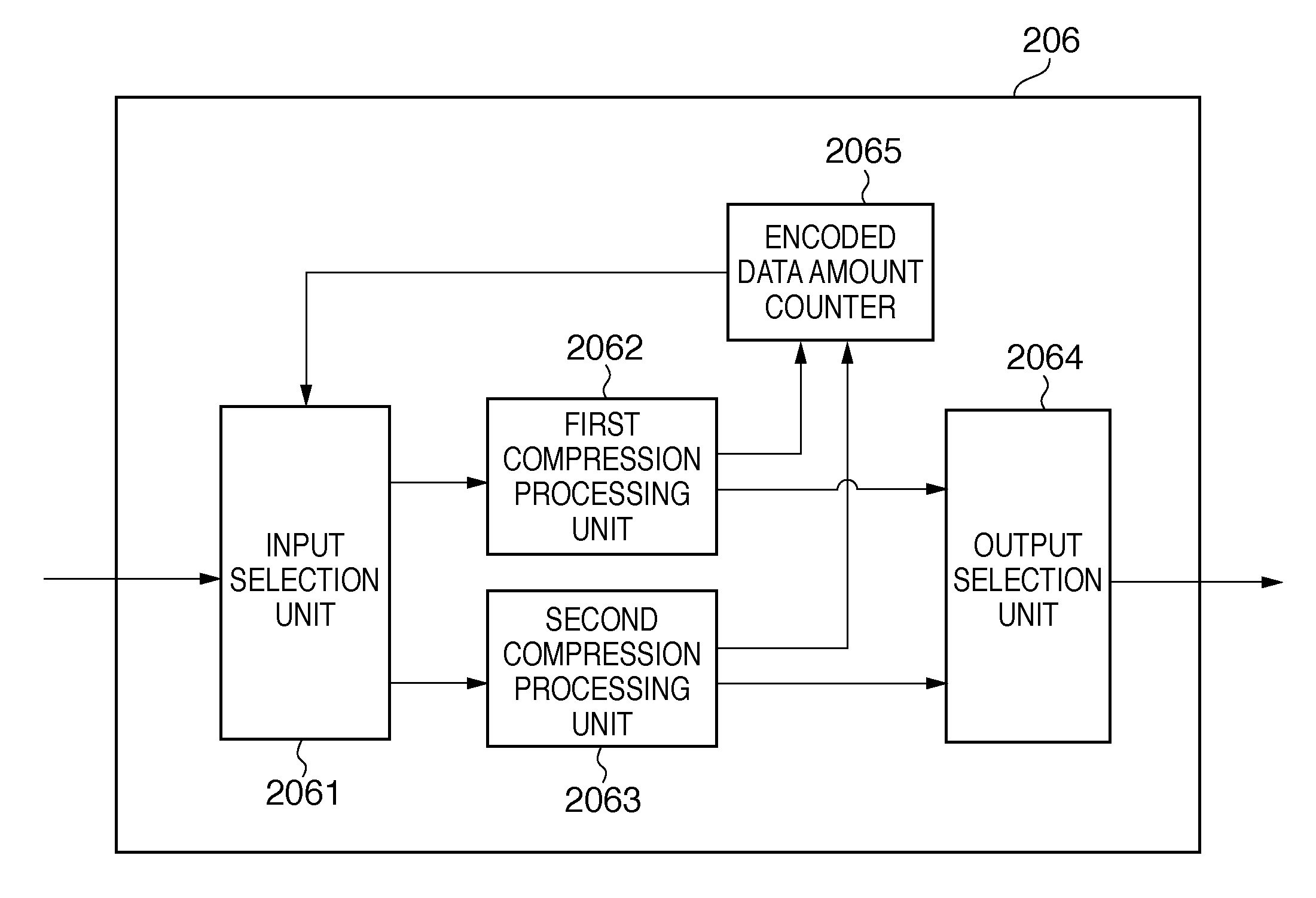
Provided is an image processing apparatus that reduces the processing time taken to encode image data that has been divided into blocks, as well as suppresses a reduction in image quality. To accomplish this, among block images obtained by dividing the image into blocks, the image processing apparatus executes encoding processing using a first method with priority on important block images such as those including thin lines or characters. Furthermore, the image processing apparatus executes encoding processing using a second method if the encoded data amount of blocks that have been encoded becomes greater than or equal to a predetermined threshold.

Description

BACKGROUND OF THE INVENTION[0001]1. Field of the Invention[0002]The present invention relates to an image processing apparatus, a control method for the same, and a program that are for compressing and encoding image data.[0003]2. Description of the Related Art[0004]Since storing high resolution image data in a memory requires a very large amount of memory to be used, it is effective to compress the image data before storing it in the memory. In image compression, compressed image data is ultimately decompressed and output, and therefore encoding is desirably performed using a variable length lossless method to prevent a loss in image quality. However, depending on the image, the lossless variable length method requires a very large amount of interpolation information in order to perform image compression. It is therefore necessary to compress the image data at a high compression rate or perform control such that the total encoded data amount falls within the memory capacity by swit...

Claims


Application Information

Patent Timeline
IPC IPC(8): G06K9/36
CPCH04N19/46H04N19/37H04N19/12H04N19/192H04N19/152H04N19/17H04N19/14
Inventor MIMA, TSUYOSHIICHIKAWA, MASANORI
Owner CANON KK
Learn More