Three-dimensional microfluidic devices
a microfluidic device and three-dimensional technology, applied in the field of three-dimensional microfluidic devices, can solve the problems of inflexible construction, and high cost of devices, and limiting the design and application of 2-d fluidic devices
- Summary
- Abstract
- Description
- Claims
- Application Information
AI Technical Summary
Benefits of technology
Problems solved by technology
Method used
Image
Examples
example 1
Patterning Paper
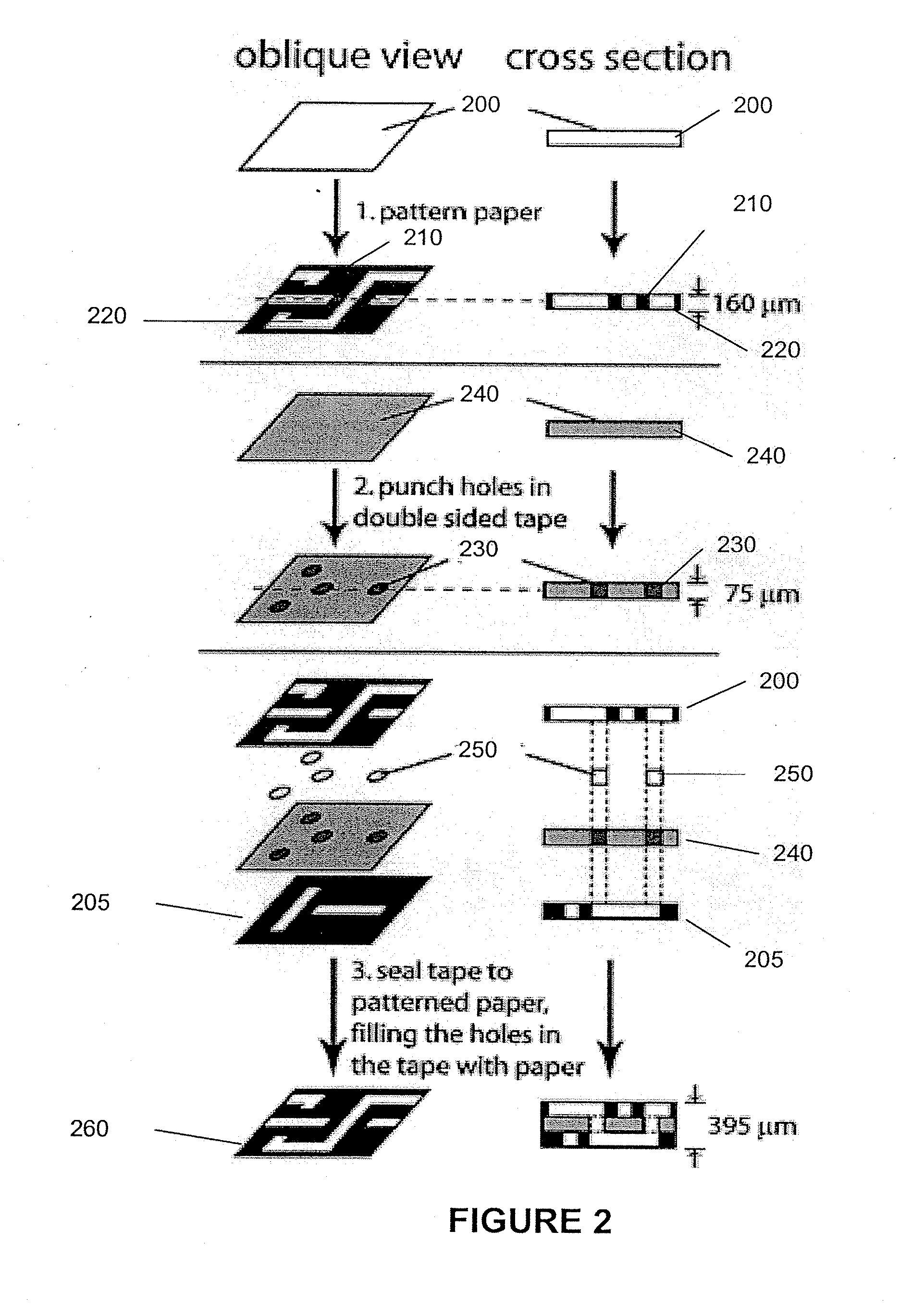
[0121]The layers of patterned hydrophilic paper are provided following the procedures described in PCT / US07 / 081,848. The patterns for the paper-based microfluidic devices were designed using the layout editor CleWin.
example 2
Microfluidic Flow Control Devices with Logic Gates
[0122]Microfluidic flow control devices with logic gates are assembled using layers of patterned hydrophilic paper and layers of fluid-impermeable medium with filled or unfilled openings described above.
[0123]Microfluidic flow control devices with AND and OR Logic Gates are described. These logic gates can be designed in 3-D paper devices using the ‘on’ button. As shown in FIG. 14, for both logic gates, two inputs A and B were designed and contain ‘on’ buttons designated by circles in the top layer of patterned paper (14A and 14E). When the inputs are compressed, they activate specific channels in the network.
[0124]The logic gates were designed with a source, where fluid is constantly supplied, two inputs A and B that are buttons, and an output, which is a well that either will fill with fluid if the input yields a true value (1), or will not fill with fluid if the input yields a false value (0). Four logic gates were placed on each ...
example 3
Microfluidic Flow Control Devices as De-Multiplexer
[0132]Microfluidic de-multiplexer is assembled using layers of patterned hydrophilic paper and layers of fluid-impermeable medium with filled or unfilled openings described above.
[0133]One of the applications of ‘on’ and ‘off’ buttons is the ability to direct fluids into specific channels or zones. A microfluidic de-multiplexer based this principle is described with reference to FIG. 18 which includes one inlet for a fluid and six different outputs. The output is controlled by an ‘on’ button that is placed next to each output. FIG. 18 shows a fluidic de-multiplexer. This device can be used to direct fluid from a single source into any number of outputs, in this case six outputs. The device is comprised of a source for fluid, six ‘on’ buttons, and six output wells. The output is determined by the buttons. FIG. 18A is a schematic of the layers in the demultiplexer, which is assembled using layers of patterned paper with defined hydrop...
PUM
| Property | Measurement | Unit |
|---|---|---|
| melting point | aaaaa | aaaaa |
| melting point | aaaaa | aaaaa |
| melting point | aaaaa | aaaaa |
Abstract
Description
Claims
Application Information
 - R&D
- Intellectual Property
- Life Sciences
- Materials
- Tech Scout
- Unparalleled Data Quality
- Higher Quality Content
- 60% Fewer Hallucinations
Browse by: Latest US Patents, China's latest patents, Technical Efficacy Thesaurus, Application Domain, Technology Topic, Popular Technical Reports.
© 2025 PatSnap. All rights reserved.Legal|Privacy policy|Modern Slavery Act Transparency Statement|Sitemap|About US| Contact US: help@patsnap.com


