Sheet Forming Device

a sheet forming and sheet technology, applied in the direction of dough shaping, manufacturing tools, applications, etc., can solve the problems of affecting the shape of the formed changing the pressure, and the variation of the nipping (rolling) amount of the material in the rolling unit, so as to facilitate the forming of the sheet at its opposing ends, the forming control can be relatively easily achieved, and the time is shorter.

Active Publication Date: 2011-05-26
MORIYAMA
View PDF3 Cites 15 Cited by
  • Summary
  • Abstract
  • Description
  • Claims
  • Application Information

AI Technical Summary

Benefits of technology

With the above-described sheet forming device according to the present invention, as the gap between the pair of rolls is increased to be greater than the planned formed thickness of the sheet, passage of the substance causing the clogging can be facilitated. In addition, as the material stored in the storing unit is pushed into between the pair of rolls while at least one of the pair of rolls is driven to rotate in the forward direction, any material remaining in the storing unit can be taken out speedily from between the pair of rolls before its viscosity changes. Hence, the trouble can be solved within a short period of time and without much trouble.
an emergency controlling means for issuing, upon detection of clogging by said clogging detecting means, a control command for operating the operational mechanism to increase the gap between the pair of rolls to a gap greater than a planned formed thickness of the sheet, a further control command for causing said rotary drive mechanism to effect forward rotary driving and a still another control command for causing the pressing mechanism to move up / down.
Further, especially if the material to be supplied to the storing unit has elasticity, a pressure distribution may develop within the storing unit. However, thanks to the provision of the pressing mechanism for pressing the material with a preset pressure (set pressure), the difference absorbing function for preventing sudden change in the inside pressure of the storing unit is provided for absorbing any difference between the receiving amount of the material from the supplying unit and the feeding amount of the material to the rolling unit, so that the sheet forming control can be effected relatively easily. In addition, even when the material has elasticity and a portion of this material tends to overflow to the outside from the top of the storing unit by pushing aside the pressing mechanism, since the pressing mechanism is moved up / down after the gap between the rolls has been increased to be greater than the planned formed thickness of the sheet, such material tending to overflow to the outside can also be pushed back to be effectively nipped between the pair of rolls. Hence, the trouble can be solved speedily and the device is effectively protected at the same time. Incidentally, as solution of such trouble can be automatically effected based on the control command from the emergency controlling means, it can be completed in even shorter time and speedily without much trouble.
Further, even when the supplying operation of the material by the supplying unit is stopped after the gap between the paired rolls has been increased, by setting the pressing force of the pressing mechanism to be higher than the normal set pressure or moving the pressing mechanism up / down in repetition, only the material in the storing unit can be taken out in a more efficient manner, so that the amount of defect material can be reduced.

Problems solved by technology

On the other hand, however, in association with such variation in the supplying amount by the supplying unit, there tends to occur change in the pressure in the material being fed to the rolling unit, which change results in variation in the nipping (rolling) amount of the material in the rolling unit.
This variation may result in such problems as disturbance in the shape of the formed sheet at its opposed ends and irregularity in the thickness thereof.
However, with such controlling of the material stored in the storing unit alone, it has been proven difficult to eliminate the variation in the nipping amount due to the variation in the pressure of the material being fed to the rolling unit.
However, in the case of material having elasticity, there occurs a pressure distribution (irregularity of the magnitude of pressure according to the position) in the pressure applied to the elastic material stored in the storing unit.
Hence, even if the receiving amount of the elastic material from the supplying unit is controlled based on detected value of the pressure applied to the elastic material at a particular position, it has been difficult to eliminate the variation in the nipping amount due to the variation in the pressure of the material to the rolling unit.
Also, in the case of the closed bank type sheet forming device, this type of device does not provide sufficiently such difference absorbing function for absorbing any difference which may have occurred between the receiving amount of the elastic material from the supplying unit and the feeding amount of the elastic material fed to the rolling unit.
Therefore, if there develops a sharp buildup in the inside pressure of the storing unit due to e.g. response performance of the control mechanism for the supplying unit, this applies significant load to the constituting members of the supplying unit and / or the rolling unit, thus inviting damage to the device.
Moreover, in the case of the closed bank type sheet forming device, for effecting inspection, cleaning of its storing unit, the device needs to be disassembled, thus requiring much trouble.
However, if there occurs a problem or deficiency in the kneading operation and / or inappropriateness of the kneading temperature, there may occur deficiency in the plasticization, which results in turn in formation of hard portions, which in turn leads to application of an excessive load to the rolling unit or failure to nip the material due to slippage of the material, thus leading to failure in rolling of the material in the rolling unit or clogging of the material in the rolling unit.
Moreover, such trouble in the sheet forming device may cause a trouble in a device operation-wise subsequent thereto, so that the entire sheet forming device needs to be temporarily stopped in its operation.
Then, the material stored in the storing unit is hardened, so that when the operation is resumed, material clogging may occur in the rolling unit.
That is, with these conventional solutions, the solutions required too much trouble and also, while the device is stopped, there occurs change in the viscosity of the material which change increases the viscosity, which makes the removal of the clogged material even more difficult to the disadvantage of the solution of the trouble.Patent Document 1: Japanese Published Patent No. Hei. 2-42331Patent Document 2: Japanese Patent Application “Kokai” No. Hei. 5-104607Patent Document 3: Japanese Patent Application “Kokai” No. 2006-231582 (paragraph 0044).

Method used


Image

  • Sheet Forming Device
  • Sheet Forming Device
  • Sheet Forming Device

Examples


first embodiment

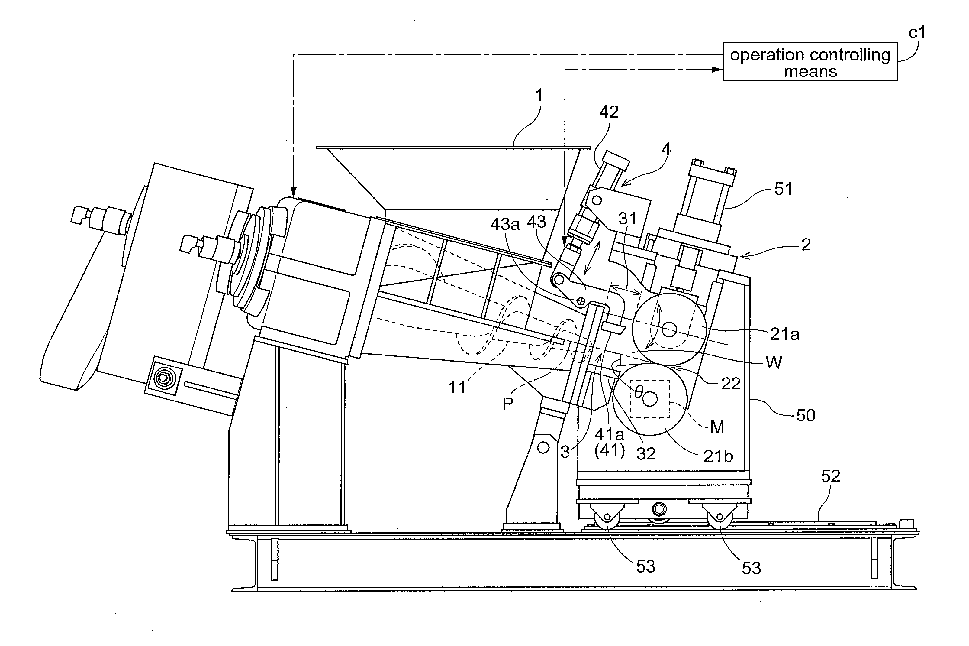
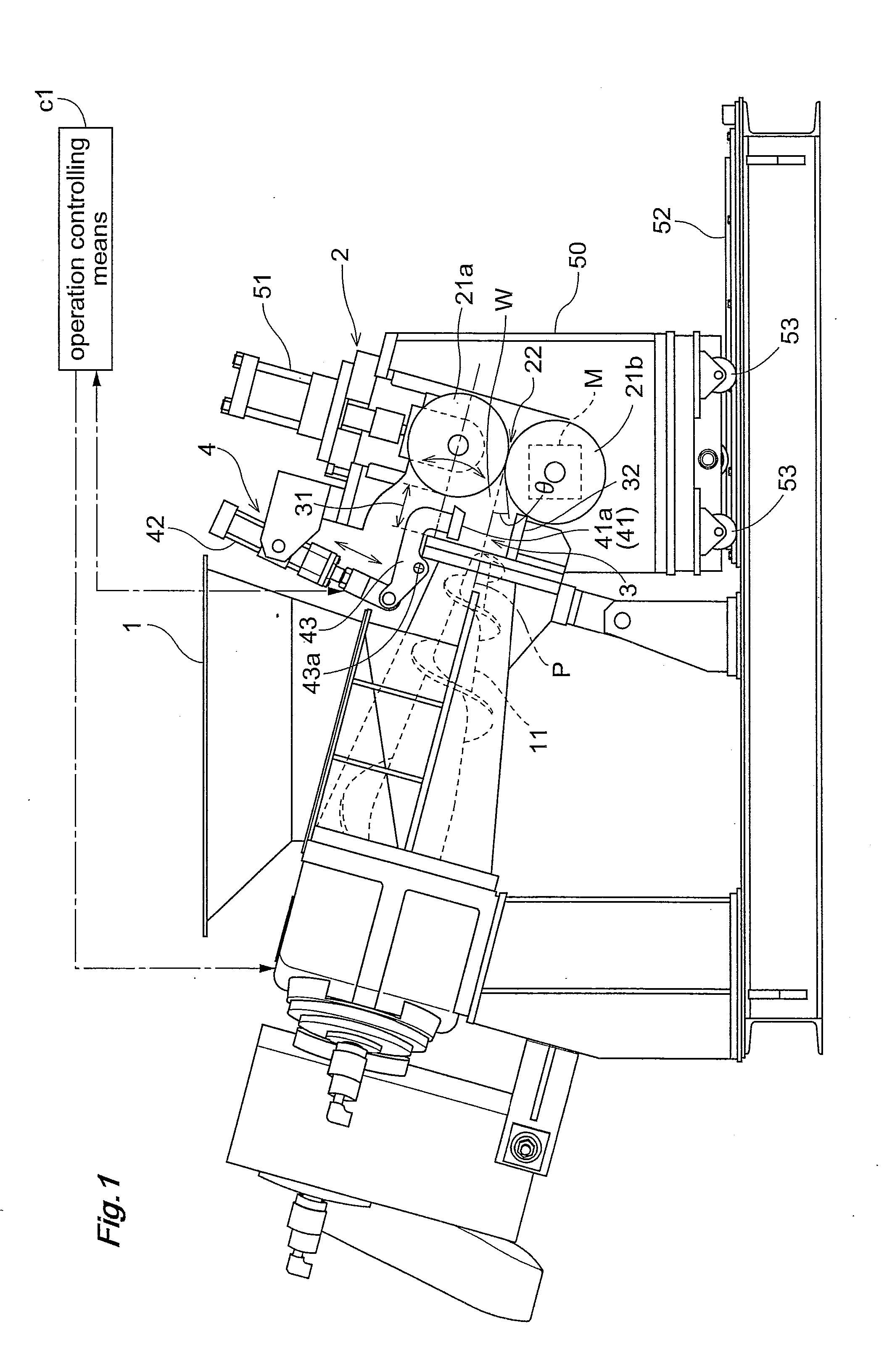
FIG. 1 shows a first embodiment of the sheet forming device relating to the present invention.

This sheet forming device includes a supplying unit 1 for supplying (extruding) plastically deformable material W, a storing unit 3 for temporality storing an amount of material W supplied (extruded) from the supplying unit 1, and a rolling unit 2 for rolling the material W stored in the storing unit 3 into a sheet form.

Like the conventional sheet forming device, in this sheet forming device, the supplying unit 1 includes an extruder 11 and the rolling unit 2 includes two rolls 21a, 21b.

In this rolling unit 2, one of the two rolls 21a, 21b is rotatably driven by a rotary drive mechanism M such as a motor and the other roll operatively coupled with the one roll via a gear is driven to rotate in operative association therewith. Alternatively, both the two rolls 21a, 21b can be driven individually by independent rotary drive mechanisms (not shown) such as motors or the like. The rolls are mou...

second embodiment

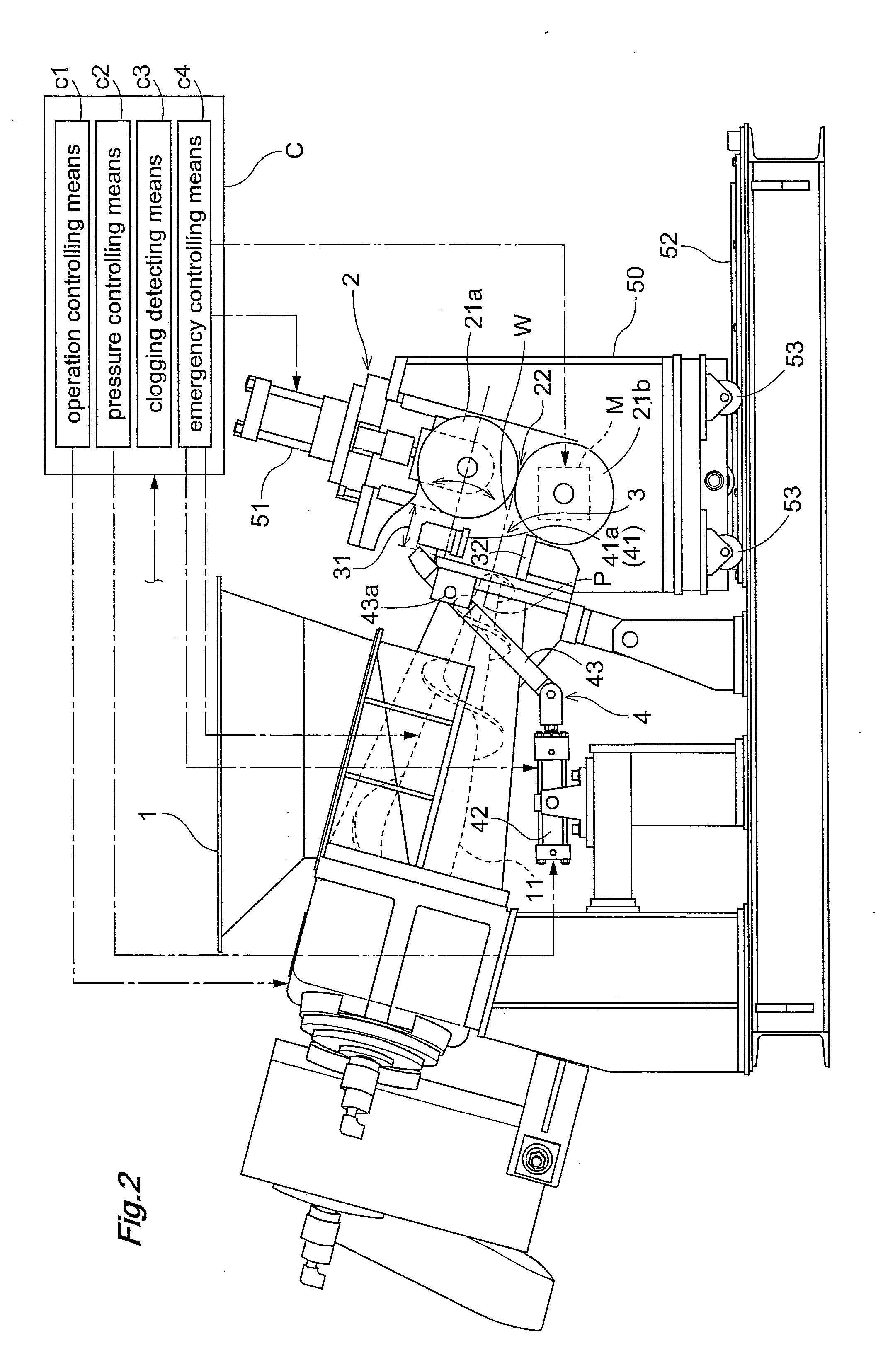
FIGS. 2 through 6 show a second embodiment of the sheet forming device relating to the present invention.

This sheet forming device, like First Embodiment, includes a supplying unit 1 for supplying rubber-like plastically deformable material W, a storing unit 3 for temporarily storing the material W supplied from the supplying unit 1, and a rolling unit 2 for rolling the material W stored in the storing unit 3.

And, in this sheet forming device too, there is provided a pressing mechanism 4 for pressing the material W stored in the storing unit 3 from its upper side with a present predetermined pressure. And, the area of the pressing face 41a of the pressing member 41 constituting the pressing mechanism 4 is set to be from 30 to 95% of the area of the upper opening portion 31 of the storing unit 3, or to from 85 to 95% in case it is needed to prevent overflowing of the material W.

Incidentally in this embodiment, like members to those in First Embodiment are denoted with like reference ...


PUM

PropertyMeasurementUnit
angleaaaaaaaaaa
angleaaaaaaaaaa
pressureaaaaaaaaaa

Abstract

In a sheet forming device having a supplying unit (1) for extruding an amount of plastically deformable material (W), a storing unit (3) for temporally storing the material (W) extruded from the supplying unit (1), and a rolling unit (2) for rolling the material (W) stored in the storing unit (3) into a sheet form, the device comprises a pressing mechanism (4) for pressing the material (W) stored in the storing unit (3) from the upper side thereof with a preset pressure, wherein a pressing member (41) constituting the pressing mechanism (4) has a pressing face (41a) whose area is set to from 30 to 95% of the area of an upper opening portion (31) of the storing unit (3).

Description

TECHNICAL FIELDThe present invention relates to a sheet forming device, more particularly to a sheet forming device configured to form, into a sheet form, a plastically deformable material such as rubber, resin, etc. (may be referred to simply as “material” hereinafter).BACKGROUND ARTConventionally, there is known a sheet forming device configured to extrude an amount of material kneaded by a kneading machine of a double tapered screw type acting as a supplying unit and to roll the extruded material into a sheet form, with a rolling unit having two rolls (see e.g. Patent Documents 1 and 2).The sheet forming device of the above noted type includes a supplying unit, a storing unit and a rolling unit. In operation, an amount of material is extruded from the supplying unit to the storing unit, in which the extruded material is stored for a while. Thereafter, the material is transferred to the rolling unit to be formed into a sheet of material having a planned formed sheet thickness (see...

Claims


Application Information

Patent Timeline
Patent Type & Authority Applications(United States)
IPC IPC(8): B29C47/92B29C48/08B29C48/525B29C48/92
CPCB29C43/245B29C47/92B29C47/0021B29C47/32B29C47/38B29C47/6012B29C2043/3433B29C2043/3444B29C2043/5841B29C2043/5875B29K2021/00B29C47/0019B29C47/402B29C2947/92019B29C2947/92076B29C2947/92295B29C2947/92514B29C2947/926B29C43/34B29B7/484B29B7/489B29B7/582B29B7/72B29B7/7495B29C48/92B29C48/07B29C48/08B29C48/35B29C48/395B29C48/402B29C2948/92019B29C2948/92076B29C2948/92295B29C2948/92514B29C2948/926B29B7/488B29B7/52B29C48/525B29C43/24B29K2101/12
Inventor MATSUMOTO, SHINICHIIRIE, MAKOTOSAIUCHI, SHIGETO
Owner MORIYAMA
Why Eureka
Try Eureka