
Centrifugal micro-fluidic device and method for detecting target in fluid sample

a microfluidic device and centrifugal technology, applied in the direction of positive displacement liquid engine, laboratory glassware, instruments, etc., can solve the problems of requiring an extended time for tests, requiring expensive automatic analysis equipment, and requiring multiple examinations at the same tim

Inactive Publication Date: 2011-05-26
SAMSUNG ELECTRONICS CO LTD
View PDF6 Cites 47 Cited by
  • Summary
  • Abstract
  • Description
  • Claims
  • Application Information

AI Technical Summary

Benefits of technology

[0024]The blood test system may further include a first control chamber to determine a concentration of the first binder prior to its contact with the target material. The blood test system may even further include a second control chamber to receive a control binder which is homologous to the first or second binder but does not bind to the target material.
[0025]In accordance to another embodiment, there is disclosed an immunosorbent assay method using a micro-fluidic device, including: providing a micro-fluidic device containing: a rotational body; a micro-fluidic structure placed on the rotational body, having multiple chambers, multiple channels through which a fluid flows between the multiple chambers, and multiple valves arranged in the channels to control a flow of the fluid, wherein the fluid is transported via centrifugal force generated by rotation of the rotational body; and a first binder provided in a first chamber of the multiple chamber in the micro-fluidic structure wherein the binder includes a first capture material that specifically binds to a first site of a target material to be detected and a first solid particle; loading a fluid sample to the micro-fluidic device to bring the sample to be in contact with the first binder for a sufficient time to allow forming a complex of the first binder and a target material contained in the sample; rotating the micro-fluidic device to separate the complex as a precipitate from the sample, producing a supernatant and the precipitate; and determining optical properties of the supernatant and/or the precipitate.
[0026]In another embodiment, described is an immunoso

Problems solved by technology

However, the foregoing method requires expensive automatic analysis equipment including, for example, spectrometers, cuvettes, liquid handlers, centrifuge units, etc. and numerous manual operations.
In order to perform a rapid test, a skilled medical lab technician is needed and, although the skilled medical lab technician conducts the test, it is very difficult to attain several examinations at the same time.
However, immunosorbent assay using a conventional disk type micro-fluidic device can detect a few analytes in a single platform since the device has a complex micro-fluidic structure formed therein.
It also requires an extended time for tests because of complicated process for carrying out a series of steps.
Therefore, such apparatus is useful for only one of the foregoing assays, thus not attaining compatibility thereof.

Method used


Image

  • Centrifugal micro-fluidic device and method for detecting target in fluid sample
  • Centrifugal micro-fluidic device and method for detecting target in fluid sample
  • Centrifugal micro-fluidic device and method for detecting target in fluid sample

Examples


Embodiment Construction

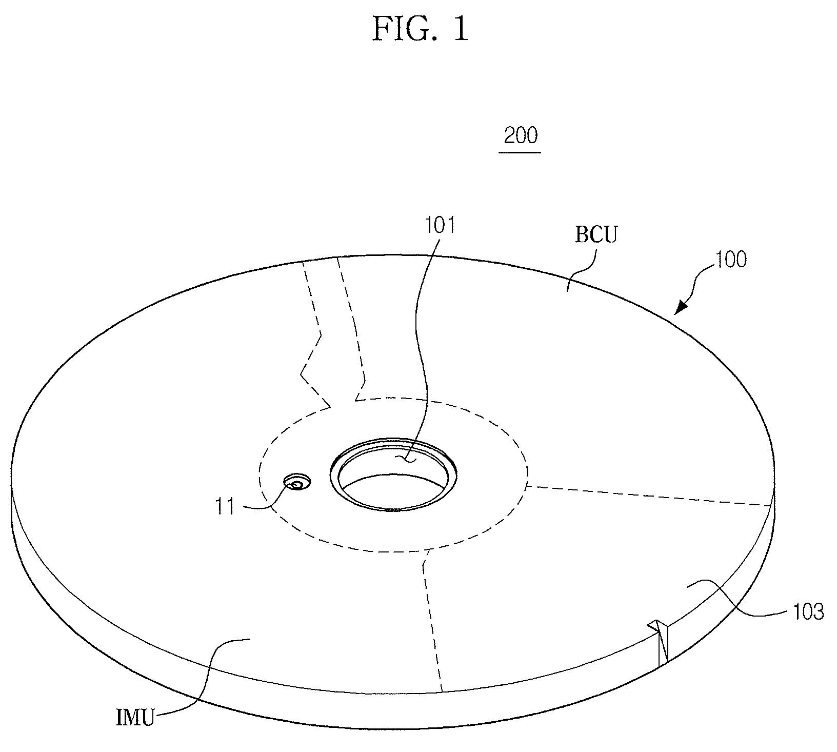
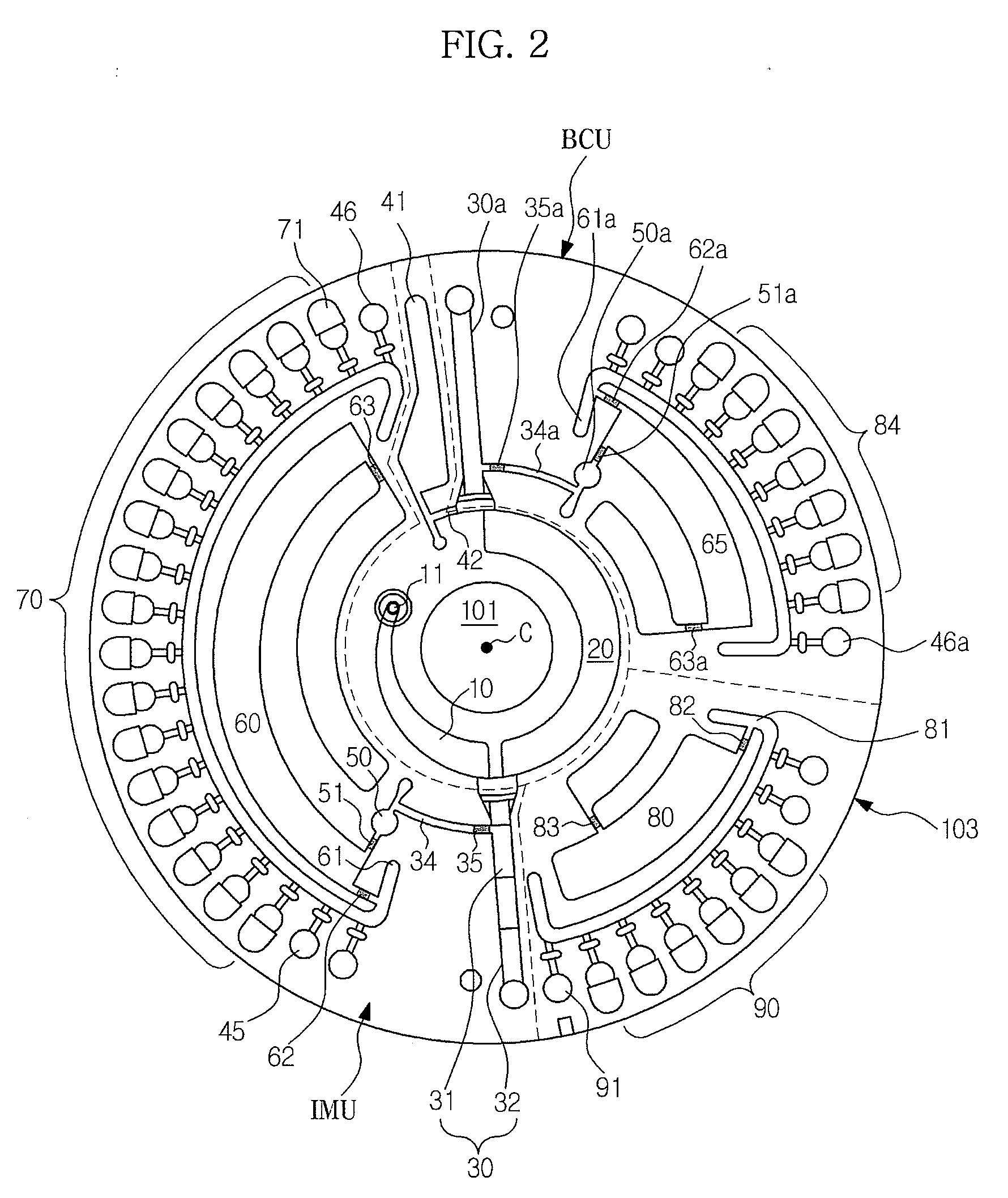
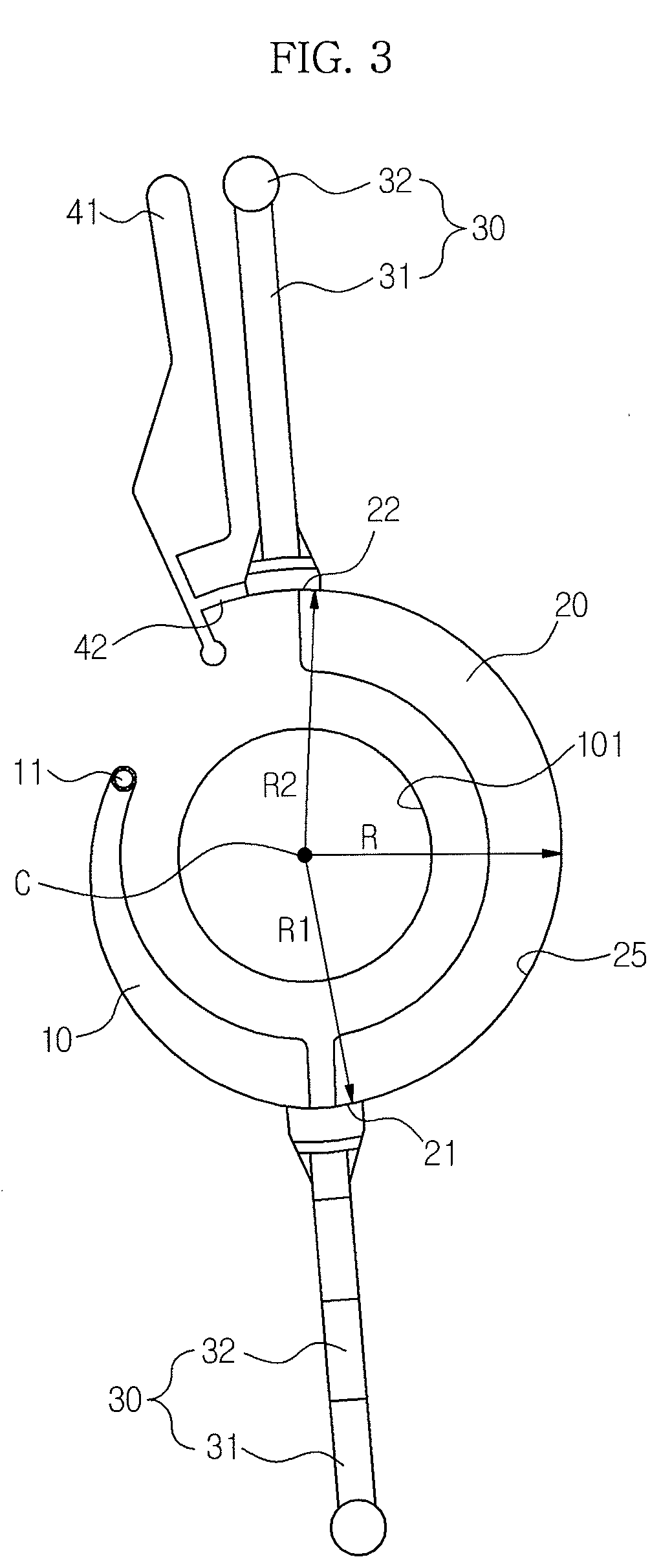
[0036]Hereinafter, advantageous features and characteristics of embodiments and practical methods thereof will be clearly understood by the following detailed description with reference to the accompanying drawings. In this regard, configuration components such as a chamber or channel shown in the drawings are simply illustrated and may be scaled up or down, thus not corresponding to real sizes thereof. In terms ‘micro-fluidic device,’‘micro-particle,’ etc., the prefix “micro-” was used herein only in contrast with “macro-” and does not limitedly refer to a unit of size.

[0037]‘Micro-fluidic structure’ used herein means a structure including various microstructural elements such as plural chambers, channels and / or valves in order to flow a fluid, rather than a specific form of structure. Therefore, ‘micro-fluidic structure’ may form a unit device to attain different functions based on features in arrangement of chambers, channels and valves and types or kinds of materials contained t...


PUM


Abstract

Disclosed are a centrifugal micro-fluidic device and an immunosorbent assay method using the same. In particular, a centrifugal micro-fluidic device having a plurality of micro-fluidic structures placed in a disc type platform to simultaneously conduct several immunosorbent assays, as well as an immunosorbent assay method using the same are provided.

Description

CROSS-REFERENCE TO RELATED APPLICATION[0001]This application claims the priority from Korean Patent Application No. 2009-114920 filed on Nov. 26, 2009 with the Korean Intellectual Property Office, the disclosure of which is incorporated herein by reference.BACKGROUND[0002]1. Field[0003]Embodiments relate to a centrifugal micro-fluidic device and an immunosorbent assay method using the same. More particularly, the centrifugal micro-fluidic device has a plurality of micro-fluidic structures arranged in a disc type platform to simultaneously conduct several immunosorbent assays.[0004]2. Description of the Related Art[0005]Among conventional methods for immunological measurement of target materials, which are contained in a liquid sample such as blood or bodily fluid, a particle-enhanced immunoassay method has been widely used. In the method, insoluble particles fixed to an antibody or antigen are mixed with a target material contained in the sample to cause immuno-agglutination via ant...

Claims


Application Information

Patent Timeline
IPC IPC(8): G01N33/553G01N30/00B01L3/00C12M1/34G01N27/00G01N21/00G01N21/76
CPCB01L3/50273B01L3/502753B01L2300/0806B01L2300/0864B01L2300/0867G01N35/00069B01L2400/0409G01N21/07G01N33/54313G01N33/54346B01L2300/087G01N33/53G01N35/10
Inventor KIM, IN WOOKLEE, BEOM SEOKKIM, KUI HYUNKIM, JI WON
Owner SAMSUNG ELECTRONICS CO LTD
Learn More