Acceleration-Primed Valving System for Centrifugal Microfluidics

a valving system and centrifugal microfluidic technology, applied in fluid controllers, laboratory glassware, laboratory apparatus, etc., can solve the problems of inability to retain liquids in the chamber at low rotational velocities, inability to manually determine the cellular/biological content of various types of samples, and in particular samples that contain living cells

Active Publication Date: 2019-03-28
RADISENS DIAGNOSTICS
View PDF0 Cites 2 Cited by
  • Summary
  • Abstract
  • Description
  • Claims
  • Application Information

AI Technical Summary

Benefits of technology

[0038]For cases where the surface is hydrophobic, siphons do not prime as described in the art. This acceleration-primed valve is primed through rapid acceleration, generating a pressure pulse that primes the acceleration-primed valve or defeats capillary valves, based on the following steps: centrifugation to high speed breaks a retaining capillary valve that preven

Problems solved by technology

Manual processing to determine the cellular/biological content of various types of samples, and in particular samples that contain living cells, is cost-prohibitive in many applications and is also prone to errors.
Automation is also cost-prohibitive in many applications, and is inappropriate as currently practiced—using, for example, liquid handling robots—for applications such as point-of-care or doctor

Method used


Image

  • Acceleration-Primed Valving System for Centrifugal Microfluidics
  • Acceleration-Primed Valving System for Centrifugal Microfluidics
  • Acceleration-Primed Valving System for Centrifugal Microfluidics

Examples


Embodiment Construction

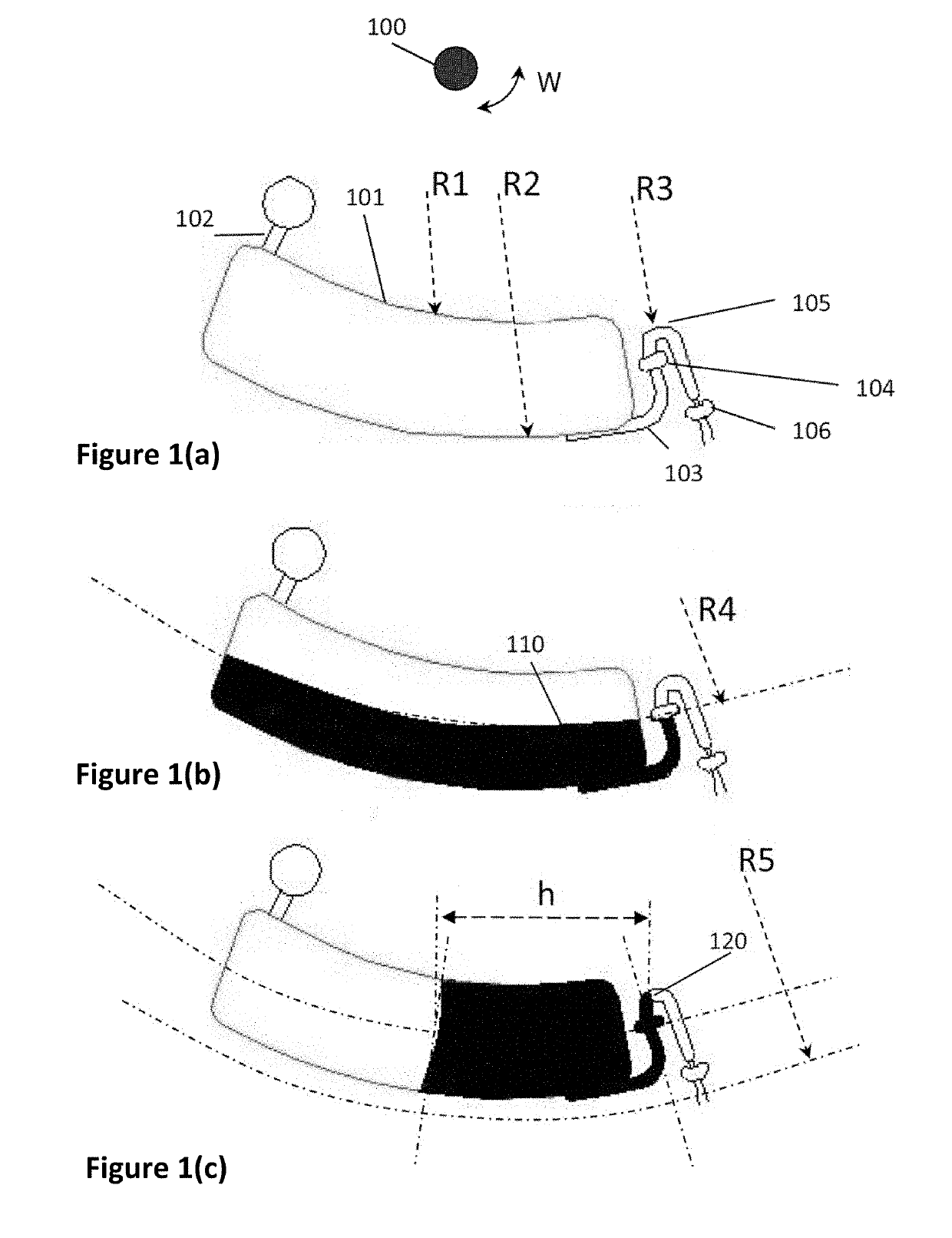
[0049]FIG. 1 presents a disc structure which provides an embodiment of an acceleration-primed valve. In FIG. 1(a), a disc rotating around a centre or axis 100 with angular velocity W comprises a holding chamber 101 dimensioned to have an inner radial wall of radius R1 and outer radial wall of radius R2, an input channel 102 and output channel 103. An acceleration-primed valve system is illustrated comprising a capillary valve 104 and a goose-neck shaped outlet channel 105, which extends radially inward from the capillary valve, having an innermost portion that is radially outward, R3, of the innermost portion of the holding chamber, R1.

[0050]An optional capillary valve 106 at the output of the outlet channel may be used to control the time at which the fluid flow is delivered to the receiving chamber once the acceleration-primed capillary valve 104 is defeated or opened.

[0051]In FIG. 1(b), the disc rotates at an initial angular velocity W1 in a clockwise direction. As illustrated, a...


PUM


Abstract

A microfluidic system for processing biological samples comprising a holding chamber adapted for holding a fluid and to be rotated on a platform, said holding chamber comprising an outlet through which fluid flow is controlled by an acceleration-primed valve system, wherein the acceleration-primed valve system comprises a capillary valve and an outlet channel. The invention provides a novel valving system, which retains fluids at low angular velocities, removes the need for hydrophilic surfaces, minimises disc real-estate and optimises certain microfluidic processes done in the holding chamber.

Description

CROSS-REFERENCE TO RELATED APPLICATIONS[0001]This is a continuation-in-part of U.S. patent application Ser. No. 14 / 649,654 filed on Jun. 4, 2015, which is the national phase under 35 U.S.C. § 371 of International Application No. PCT / EP2013 / 075736 filed on Dec. 5, 2013, which claims priority to and benefit of European Patent Application No. 12195761.7 filed on Dec. 5, 2012 and U.S. Provisional Ser. No. 61 / 733,866 filed on Dec. 5, 2012, the entire disclosures of each of which are incorporated by reference herein.FIELD OF THE INVENTION[0002]The invention relates to a new valving system related to a microfluidic disc, apparatus, system and method, for use in clinical diagnostics. In particular the invention relates to an acceleration-primed valving system for use in centrifugal microfluidic platforms.BACKGROUND[0003]Manual processing to determine the cellular / biological content of various types of samples, and in particular samples that contain living cells, is cost-prohibitive in many ...

Claims


Application Information

Patent Timeline
IPC IPC(8): B01L3/00
CPCB01L3/502738B01L3/50273B01L2200/06B01L2400/0409B01L2400/0406B01L2200/0605B01L2200/0652B01L2300/0803B01L2300/087B01L2400/0688
Inventor KELLOGG, GREGORY J.DOOLAN, DAVIDCRONIN, DONAL
Owner RADISENS DIAGNOSTICS
Why Eureka
Try Eureka