Centrifugal micro-fluidic device for rapidly preparing liquid drops and liquid drop preparation method

A microfluidic device and droplet technology, applied in the field of biomedical materials, can solve the problems of low yield, limited droplet yield, high cost and technical requirements, and meet production needs, good monodispersity, and sphericity high effect

Pending Publication Date: 2021-07-30
NANJING DRUM TOWER HOSPITAL
View PDF0 Cites 2 Cited by
  • Summary
  • Abstract
  • Description
  • Claims
  • Application Information

AI Technical Summary

Problems solved by technology

However, due to factors such as the wettability of the microchannel and high flow resistance, the traditional shear force-based microfluidic technology usually has a low yield and is difficult to meet the requirements of high-throughput preparation; based on this, a centrifugal microfluidic technology is currently being developed. The research of fluidic technology is expected to solve the above technical problems. The current specific implementation method is usually based on the centrifugal microfluidic method of the chip, that is, the chip with complex microchannels is made by photolithography and other methods, and the precursor solution is injected into the corresponding microfluidics. The reaction in the microchannel generates droplets; although this method can prepare highly monodisperse droplets, the cost and technical requirements of this method are high, and only a small amount of precursor solution can be stored, which greatly limits the size of the droplets. Yield

Method used


Image

  • Centrifugal micro-fluidic device for rapidly preparing liquid drops and liquid drop preparation method
  • Centrifugal micro-fluidic device for rapidly preparing liquid drops and liquid drop preparation method
  • Centrifugal micro-fluidic device for rapidly preparing liquid drops and liquid drop preparation method

Examples


no. 1 example

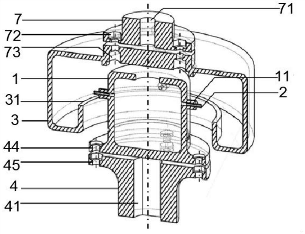
[0031] Such as figure 1 As shown, in this embodiment, a centrifugal microfluidic device for rapidly preparing droplets includes an inner reservoir 1 with a hollow inner cavity and an outer reservoir 3, the bottom of the outer reservoir 3 The end is provided with an annular boss 31 extending toward its inner cavity, and a collecting tank is provided between the annular boss 31 and the inner wall of the outer liquid reservoir 3, and the outer phase liquid is injected into the collecting tank; the inner liquid reservoir 1 is on the same centerline It is arranged in the inner cavity of the outer liquid reservoir 3 and there is a certain gap between the inner liquid reservoir 1 and the outer liquid reservoir 3; the top of the inner liquid reservoir 1 is provided with an infusion hole 12, through which the inner phase The liquid is injected into the inner liquid reservoir 1; the outer circumference of the inner liquid reservoir 1 is provided with several round tube bosses 11, and a ...

no. 2 example

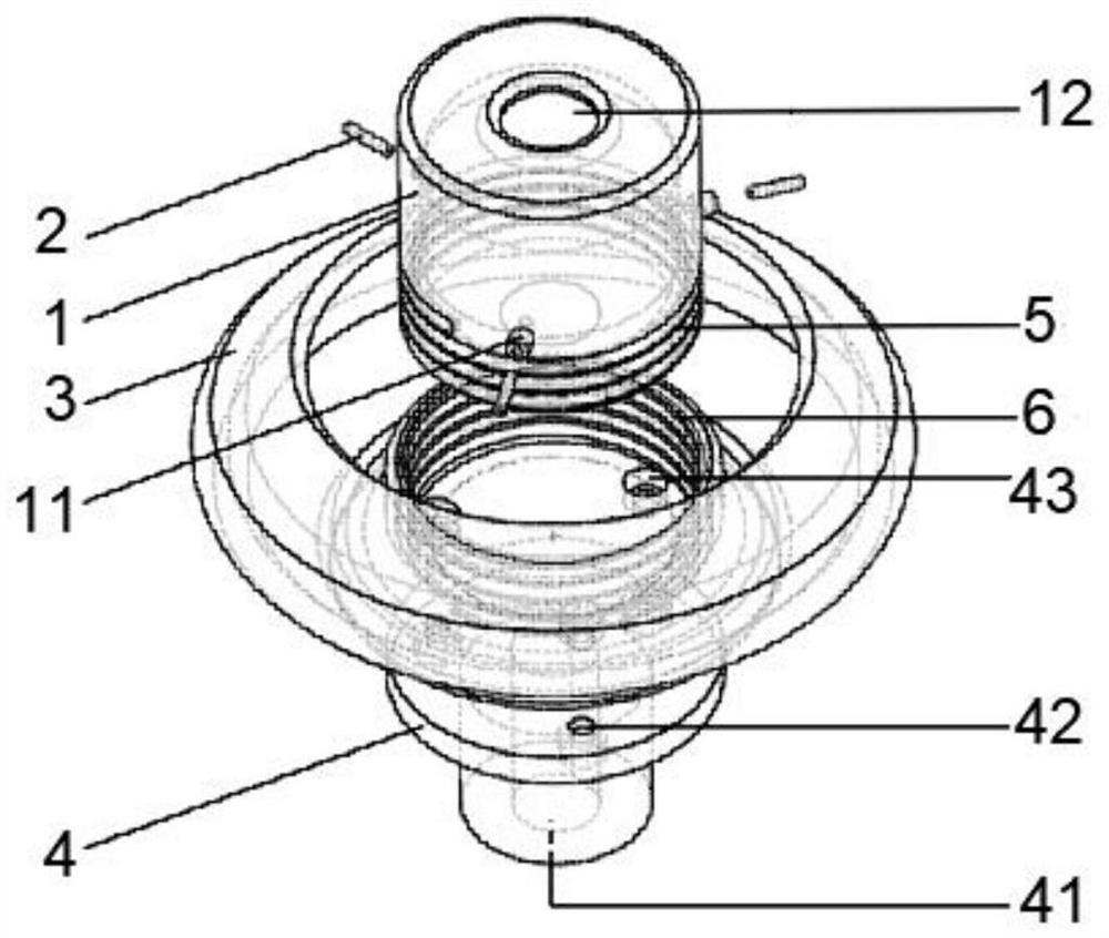
[0039] Such as figure 2 As shown, the difference between this embodiment and the first embodiment is that an external thread section 5 is provided on the outer wall of the inner liquid reservoir 1, and an internal thread section 6 is provided on the inner ring wall of the annular boss 31. The external thread section 5 is screwed into the internal thread section 6 to connect the internal liquid reservoir 1 and the external liquid reservoir 3 .

[0040] Wherein, the centrifugal transmission mechanism in this embodiment is composed of an external thread section 5, an internal thread section 6 and a combined transmission mechanism.

[0041] Wherein, the driving motor shaft sleeve 4 is equiangularly divided with several side connection holes 42, and each side connection hole 42 is equipped with a fixing piece for fixing the motor shaft; the outer liquid reservoir 3 is also provided with several vertical To the connecting holes 43, each vertical connecting hole 43 is provided with...

no. 3 example

[0048] The third embodiment: this embodiment provides a method for liquid droplet preparation based on the above device, including the following steps:

[0049] Step a: prepare the internal phase liquid and the external phase liquid, and select a capillary 2 with a suitable diameter and an internal liquid reservoir 1 with a suitable diameter according to the size requirements of the droplet preparation to complete the installation of the microfluidic device;

[0050] Step b: inject the inner phase liquid into the inner liquid reservoir 1, and inject the outer phase liquid into the collection tank between the inner walls of the outer liquid reservoir 3;

[0051] Step c: Set the rotational speed of the speed-regulating motor, use the speed-regulating motor to drive the inner liquid reservoir 1 to rotate at a high speed and further promote the centrifugal movement of the inner phase liquid in the inner liquid reservoir 1, so as to squeeze the inner phase liquid from one end of the...


PUM


Abstract

The invention discloses a centrifugal micro-fluidic device for rapidly preparing liquid drops and a liquid drop preparation method, and belongs to the technical field of biomedical materials.The centrifugal micro-fluidic device comprises an inner liquid storage device and an outer liquid storage device which are provided with hollow inner cavities, wherein inner phase liquid is injected into the inner liquid storage device, a collecting groove is formed in the bottom end of the inner cavity of the outer liquid storage device, outer phase liquid is injected into the collecting groove, and the inner liquid storage device and the center line are arranged in the inner cavity of the outer liquid storage device; a capillary tube installed on the inner liquid storage device, wherein one end of the capillary tube is communicated with the inner cavity of the inner liquid storage device, and the other end of the capillary tube is positioned above the collecting groove; and a centrifugal transmission mechanism which is connected with the inner liquid storage device and can drive the inner liquid storage device to rotate at a high speed and enable the inner phase liquid to do centrifugal motion in the inner liquid storage device, wherein centrifugal force borne by the inner phase liquid during centrifugal motion can extrude the inner phase liquid to enter the tube from one end of the capillary tube and generate liquid drops at the other end of the capillary tube. The device has the advantages that high-flux production of the liquid drops can be realized, and meanwhile, the size and the shape of the liquid drops are flexible and controllable.

Description

technical field [0001] The invention relates to the technical field of biomedical materials, in particular to a centrifugal microfluidic device for rapidly preparing liquid droplets and a method for preparing liquid droplets. Background technique [0002] Droplets have good diversity and designability, and have great application potential in the fields of chemical engineering, food industry, energy utilization, biomedical engineering, electronic cooling, and drug delivery; droplets can be transformed into various forms after processing Such as gels, microspheres, etc., these microspheres or gels have good mechanical properties, transport properties and release properties; traditional emulsification methods use high-speed stirring to disperse one solution in another solution to form A variety of droplets, the intermediate emulsion can also be further emulsified to form higher-order multi-emulsion droplets, but the above method has many problems such as inability to accurately...

Claims


Application Information

Patent Timeline
Patent Type & Authority Applications(China)
IPC IPC(8): B01L3/00B01F13/00B01J13/00B01J13/04
CPCB01L3/502784B01L3/50273B01J13/04B01J13/0052B01L2400/0409B01F33/3021
Inventor 赵远锦李金博王月桐商珞然张大淦
Owner NANJING DRUM TOWER HOSPITAL
Why Eureka
Try Eureka