Automated actuator for spring based multiple purpose medical instruments

a technology of automatic actuator and end effector, which is applied in the field of automatic actuator for use with a spring-based end effector operative instrument and endoscope, can solve the problems of adding cost and risk, complicating the operative procedure, and requiring additional operating room space for assisting sta

Inactive Publication Date: 2011-05-26
ZIMMON DAVID
View PDF19 Cites 33 Cited by
  • Summary
  • Abstract
  • Description
  • Claims
  • Application Information

AI Technical Summary

Benefits of technology

[0021]In another embodiment, the automated control device is disposed in the endoscope handle and there is a removable and replaceable actuator shaft connected outside the endoscope to a distal endoscope section. The end effector actuator passes through this removable and replaceable actuator shaft and is connected to the automated control device via a wire running through the actuator shaft. Preferably, the handle and the automated control device are separable from the shaft and the end effector, and are reusable. The end effector could be separable from the actuator shaft and be replaceable as well.
[0022]In another embodiment, the automated control device is disposed within the endoscope handle and the end effector is disposed within a distal endoscope section and is removable and replaceable. The control device is connected to the end effec

Problems solved by technology

Additionally there is the cost of the assistant and the additional operating room space required for assisting staff.
These requirements complicate the operative procedure, add cost and risk if any of the protective measures fail.
For the patient, this complexity prolongs the procedure, increases the anesthesia duration, cost and risk of operative error.
Jaw fulcrum end effectors need complex operational control systems because of the frictional re

Method used


Image

  • Automated actuator for spring based multiple purpose medical instruments
  • Automated actuator for spring based multiple purpose medical instruments
  • Automated actuator for spring based multiple purpose medical instruments

Examples


Embodiment Construction

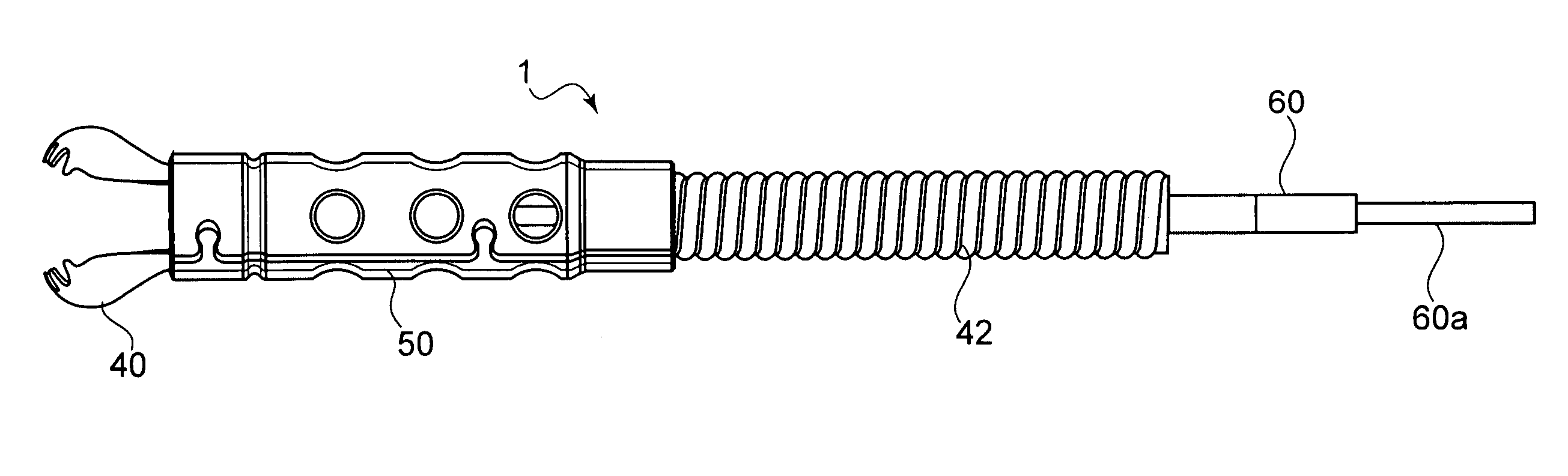
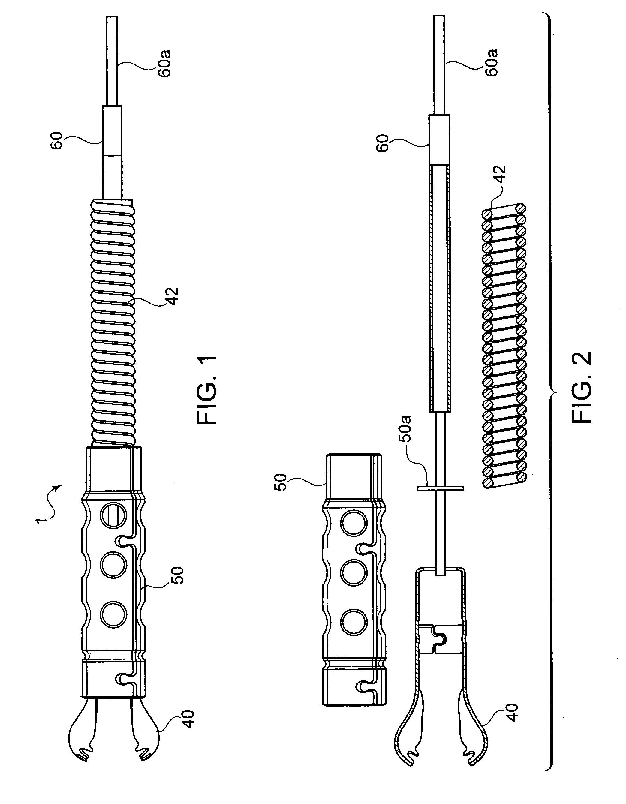
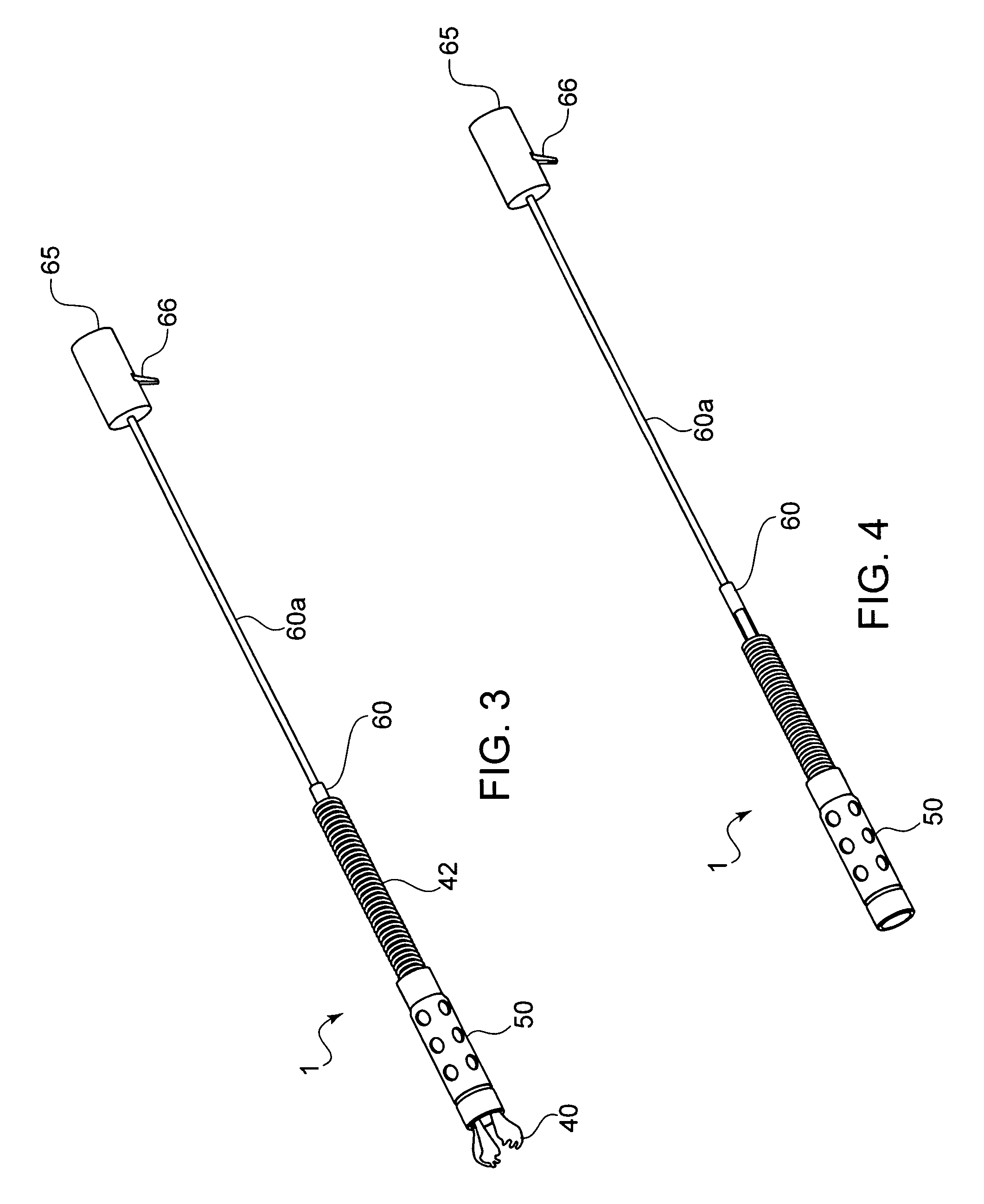
[0049]The device shown in FIGS. 1-4 comprises a spring-based biopsy end effector generally designated as 1 with an actuator wire 60a connected to spring arms 40 in a housing 50. A cable or other spacer 42 connected to automatic control mechanism 65 keeps spring arms 40 in the correct position relative to the housing 50 as shown in FIGS. 3 and 3a until actuator wire 60a is pulled to retract arms 40 within housing 50, to capture a biopsy 100, as shown in FIGS. 3a and 4. As shown in the exploded view in FIG. 2, there is an actuator extension stop 60 that prevents overextension of spring arms 40, and a housing stop 50a which prevents over-retraction by actuator wire 60a.

[0050]According to the present invention, the pulling and releasing of actuator wire 60a takes place via an automated control mechanism 65 that is actuated by an actuating device 66, shown in FIGS. 3 and 4. Control mechanism 65 can comprise any suitable automatic force generator that can pull and release actuator wire. ...


PUM


Abstract

An automated actuator for the spring-based end effector of a medical instrument to be used by a single operator without assistance for biopsy, clipping, clamping, grasping, snaring, cutting, dissecting or other operative functions with electrical connections for cautery or hot biopsy used independently or combined with a rigid or flexible endoscope of any size. The control mechanism may be a spring(s), gear(s), electrical solenoid or motor, air or hydraulic pressure activated piston or a combination thereof. Automated action may be initiated by voice, hand or foot controls. The actuating mechanism may be disposable, attached to or separable from the end effector instrument or permanently attached to be reusable. The automated instrument may be combined with an endoscope.

Description

CROSS-REFERENCE TO RELATED APPLICATIONS[0001]This application claims priority under 35 U.S.C. §119(e) of U.S. Provisional Application Ser. No. 61 / 284,230, filed on Dec. 14, 2009. This application is also a continuation-in-part under 35 U.S.C. §120 of U.S. patent application Ser. No. 11 / 435,058, filed on May 16, 2006.FIELD OF THE INVENTION[0002]The present invention relates to an automated actuator for use with a spring-based end effector operative instrument and endoscope for medical procedures including biopsy, clipping, clamping, grasping, snaring, cutting, dissecting or other actions.PRIOR ART[0003]It is often necessary to perform operative procedures through small access sites deep into a lumen or a cavity. These operations are performed by insertion of flexible or rigid instruments using palpation, visual, endoscopic or radiologic imaging control including fluoroscopy, magnetic resonance or ultrasound. The shaft or handle is used to advance or withdraw the instrument by hand. T...

Claims


Application Information

Patent Timeline
IPC IPC(8): A61B1/00
CPCA61B1/00002A61B10/04A61B10/06A61B17/29A61B17/295A61B2017/00292A61B2010/0208A61B2017/320064A61B1/00105A61B1/00133A61B1/018A61B17/32056A61B2017/00296A61B1/0053A61B2560/0493
Inventor ZIMMON, DAVID
Owner ZIMMON DAVID
Why Eureka
Try Eureka