
Control method for a robot vehicle, and robot vehicle

a robot vehicle and control method technology, applied in the direction of process and machine control, distance measurement, instruments, etc., can solve the problems of inability to guarantee the complete coverage of the working area, affecting the accuracy of standard gps receivers, and presenting technical barriers, so as to improve the manicured appearance of the lawn, improve the accuracy of section navigation, and improve the individual position estimation

Active Publication Date: 2011-05-26
ROBERT BOSCH GMBH
View PDF8 Cites 13 Cited by
  • Summary
  • Abstract
  • Description
  • Claims
  • Application Information

AI Technical Summary

Benefits of technology

The invention is a control method for autonomous robot vehicles, particularly lawn mowing vehicles, that optimizes their navigation and reduces the number of multiple traverses in their working area. The method uses a combination of dead reckoning and GPS signals to measure the vehicle's position and progress through the working area. The driving means of the robot vehicle are controlled in a way that minimizes the number of turns and the distance between parallel course sections. This results in a more efficient coverage of the working area and reduces energy consumption. The invention also provides a section travel strategy that coordinates the individual sections to minimize the overlap of their course sections and improve the manicured appearance of the lawn. The driving means are controlled to initiate a change in direction of the robot vehicle when a position estimation error no longer lies with a predefined probability. The section travel strategy is algorithmically implemented with a standard deviation of the position estimation error.

Problems solved by technology

There is thus no guarantee for a complete coverage of the working area.
Such an accurate positioning nowadays represents, however, a technical barrier.
Standard GPS receivers are thus considerably less accurate, and other technologies are too cost intensive and too susceptible to breakdown or require a complex installation, such as for instance the use of known landmarks from the British patent GB 2 277 152 A1.
It is, however, in this case disadvantageous that the position estimation error, which occurs transversely to the direction of travel of the robot vehicle, grows without bounds as the path length increases so that traversing the entire working area solely on the basis of dead reckoning is equivalent to random navigation.

Method used


Image

  • Control method for a robot vehicle, and robot vehicle
  • Control method for a robot vehicle, and robot vehicle

Examples


Embodiment Construction

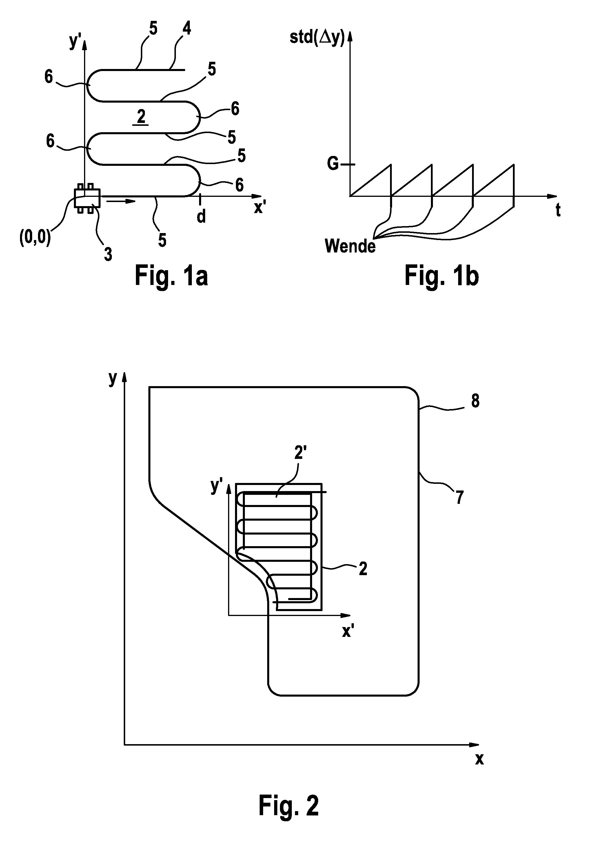
[0027]Elements which are the same and elements having the same function are labeled in the figures with the same reference numerals.

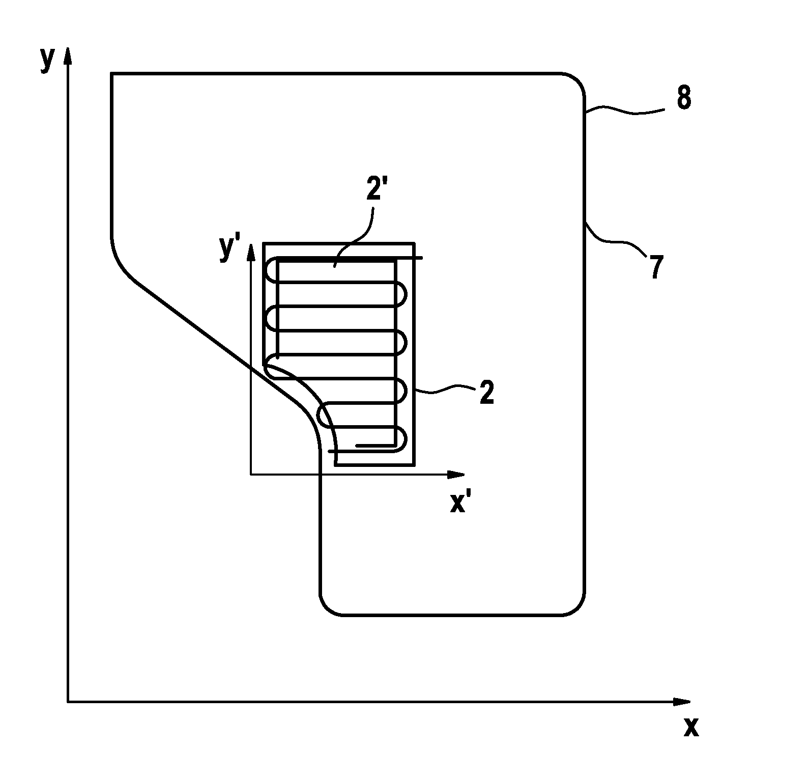
[0028]In FIG. 1a, a section 2 is schematically depicted in a sectional Cartesian coordinate system 1 (x′, y′). A robot vehicle 3 travels through said section 2 according to a section travel strategy with a sinuous movement pattern 4. The movement pattern 4 comprises a plurality of course sections 5 which are substantially parallel to each other, wherein two adjoining course sections 5 are in each case connected to each other via in each case a 180E turnaround 6 (turnaround course section). The direction of travel of the robot vehicle 3 along the course sections 5 takes place along the x′ axis. A position estimation error in the y′ direction, i.e. transversely to the direction of travel, is continually ascertained by dead reckoning—likewise the associated standard deviation std (Δy).

[0029]The distance d is plotted on the x′ axis, whereat the robot vehicl...


PUM


Abstract

The invention relates to a method for controlling driving means which are designed to steer and move a robot vehicle (3) that is particularly designed as a lawn mowing vehicle. In said control method, the driving means are controlled in such a way that the robot vehicle (3) travels through several sections (2) of a working area (8) in a specific movement pattern according to a section travel strategy with the help of dead reckoning such that two adjoining course sections (5) overlap with a predefined probability transversely to the direction of travel of the robot vehicle (3). The invention further relates to a robot vehicle (3).

Description

TECHNICAL FIELD[0001]The invention relates to a method for controlling driving means which are designed to steer and move a robot vehicle on a working area according to claim 1 as well as to a robot vehicle, in particular a lawn mowing vehicle, according to claim 14.[0002]Autonomous lawn mowers currently available on the market navigate by means of random navigation. This is fraught with several disadvantages. There is thus no guarantee for a complete coverage of the working area. Numerous multiple traverses by the mower leave the lawn having an unaesthetic appearance. An advantageous global positioning of the robot vehicle having an accuracy with a margin of error less than 5 cm could allow for an optimal travel strategy. Such an accurate positioning nowadays represents, however, a technical barrier. Standard GPS receivers are thus considerably less accurate, and other technologies are too cost intensive and too susceptible to breakdown or require a complex installation, such as fo...

Claims


Application Information

Patent Timeline
Patent Type & Authority Applications(United States)
IPC IPC(8): G05D1/02
CPCA01D34/008G05D1/0219G05D2201/0208G05D1/0278G05D1/0272
Inventor BIBER, PETERALBERT, AMOS
Owner ROBERT BOSCH GMBH
Learn More