
Exhaust pipe structure of vehicle

a technology of exhaust pipe system and vehicle, which is applied in the direction of mechanical equipment, machines/engines, transportation and packaging, etc., can solve the problems of reduced exhaust efficiency of combustion gas and malfunction of underbody catalytic converter, so as to improve start acceleration and drivability, reduce exhaust interference, and improve torque and fuel efficiency of engines

Active Publication Date: 2011-06-02
HYUNDAI MOTOR CO LTD +1
View PDF9 Cites 3 Cited by
  • Summary
  • Abstract
  • Description
  • Claims
  • Application Information

AI Technical Summary

Benefits of technology

[0021]The present invention having the configuration described above has the advantage of improving torque and fuel efficiency of an engine at low-speed and middle-speed regions by reducing exhaust interference, and improving start acceleration and drivability by the increase of torque.
[0022]Since two semicircular pipes manufactured by hydro-forming are in surface contact with each other in the exhaust pipe, performance is improved, but volume is not increased, as compared with exhaust pipes of the related art, such that it is advantageous in the space availability respect.
[0023]Further, it has the advantage of delivering combustion gas without loosing temperature to the underbody catalytic converter with one pipe.

Problems solved by technology

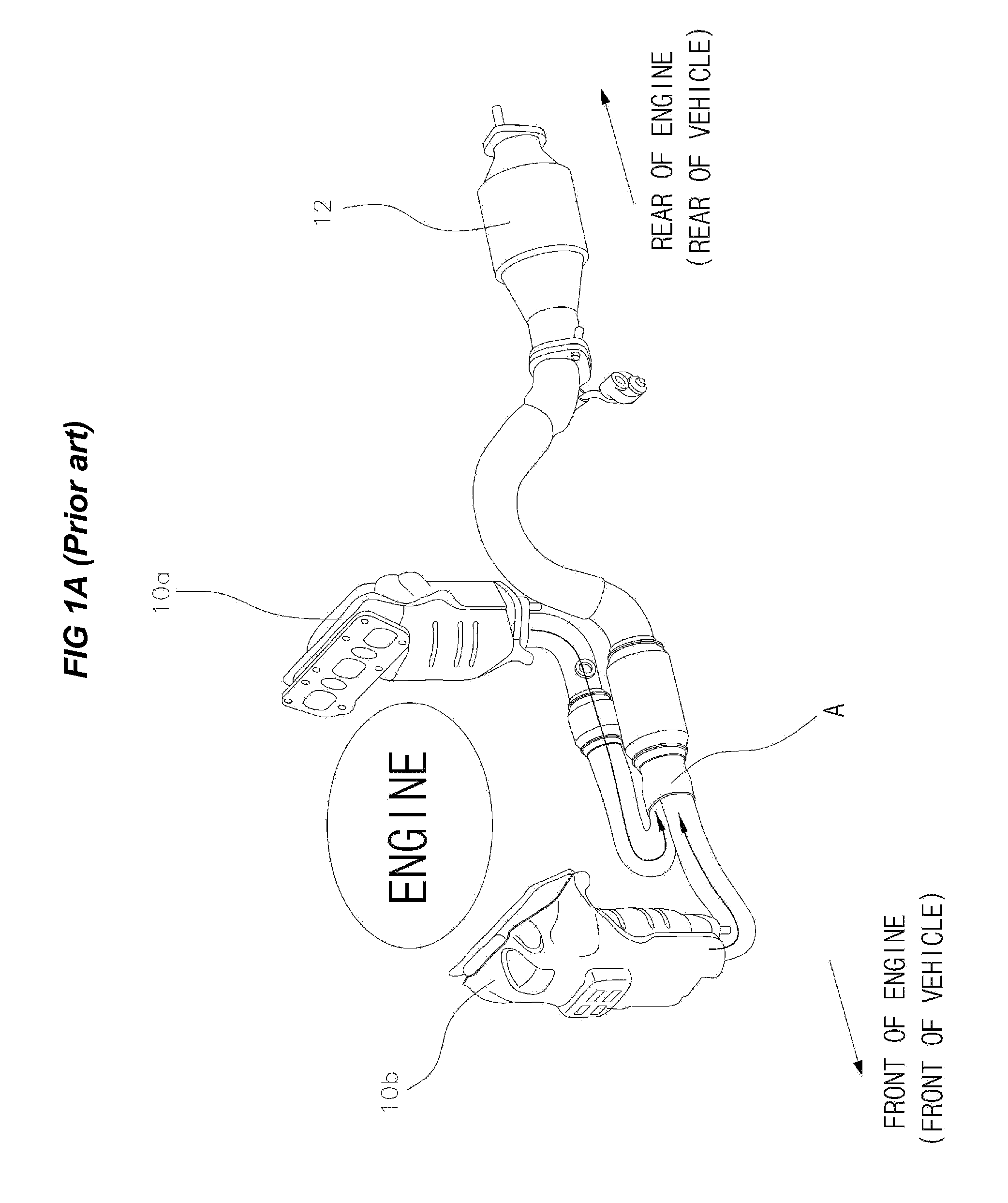
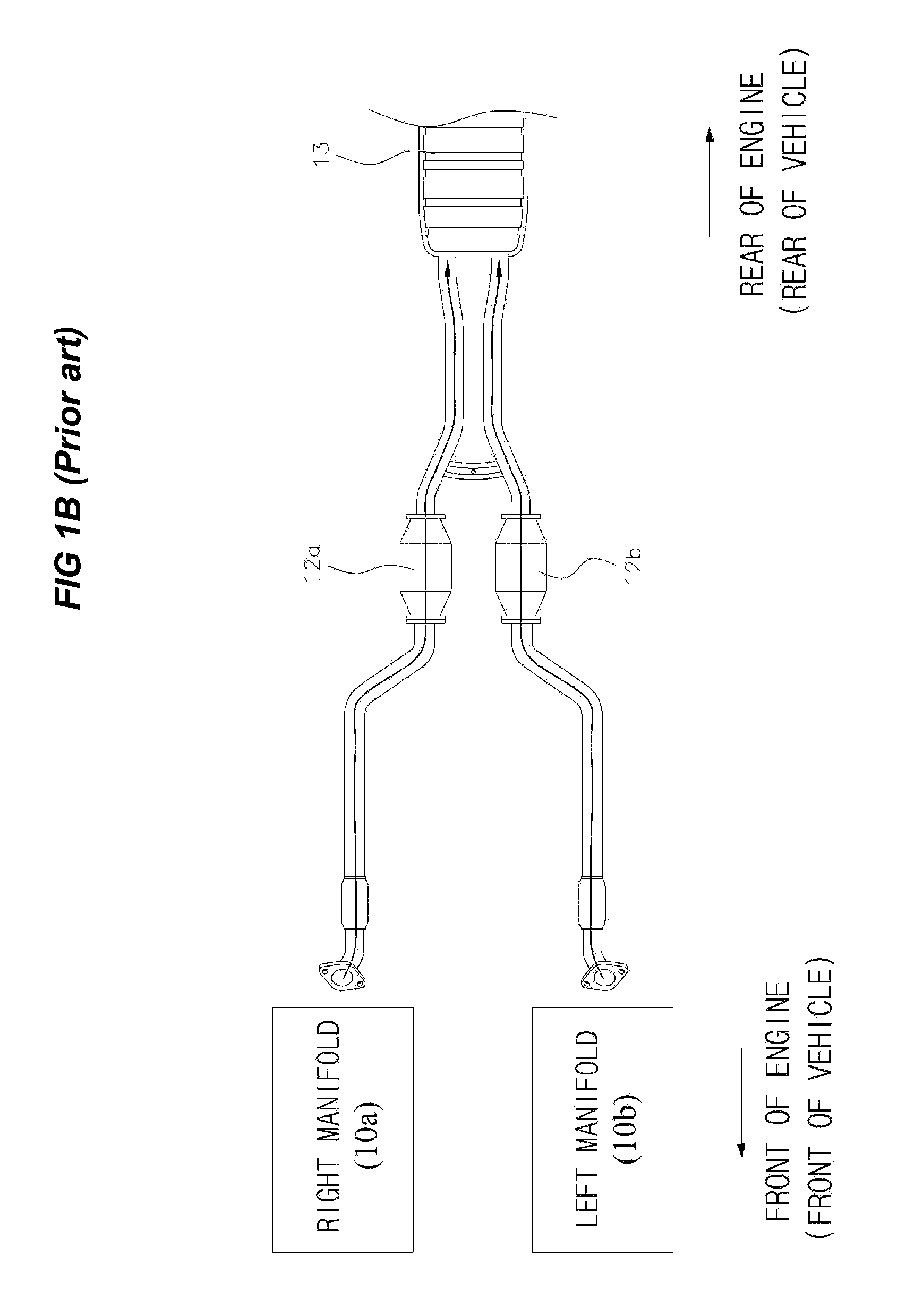
Exhaust efficiency of combustion gas is reduced, for example, when combustion gas discharged out of a cylinder interferes with combustion gas discharged out of another cylinder gas and flowing through an exhaust pipe.
Further, although it is possible to reduce exhaust interference by disposing an underbody catalytic converter at a predetermined rear position and the conjunction behind the underbody catalytic converter, in this configuration, the underbody catalytic converter may malfunction due to temperature drop of exhaust gas.

Method used


Image

  • Exhaust pipe structure of vehicle
  • Exhaust pipe structure of vehicle
  • Exhaust pipe structure of vehicle

Examples


Embodiment Construction

[0033]Reference will now be made in detail to various embodiments of the present invention(s), examples of which are illustrated in the accompanying drawings and described below. While the invention(s) will be described in conjunction with exemplary embodiments, it will be understood that present description is not intended to limit the invention(s) to those exemplary embodiments. On the contrary, the invention(s) is / are intended to cover not only the exemplary embodiments, but also various alternatives, modifications, equivalents and other embodiments, which may be included within the spirit and scope of the invention as defined by the appended claims.

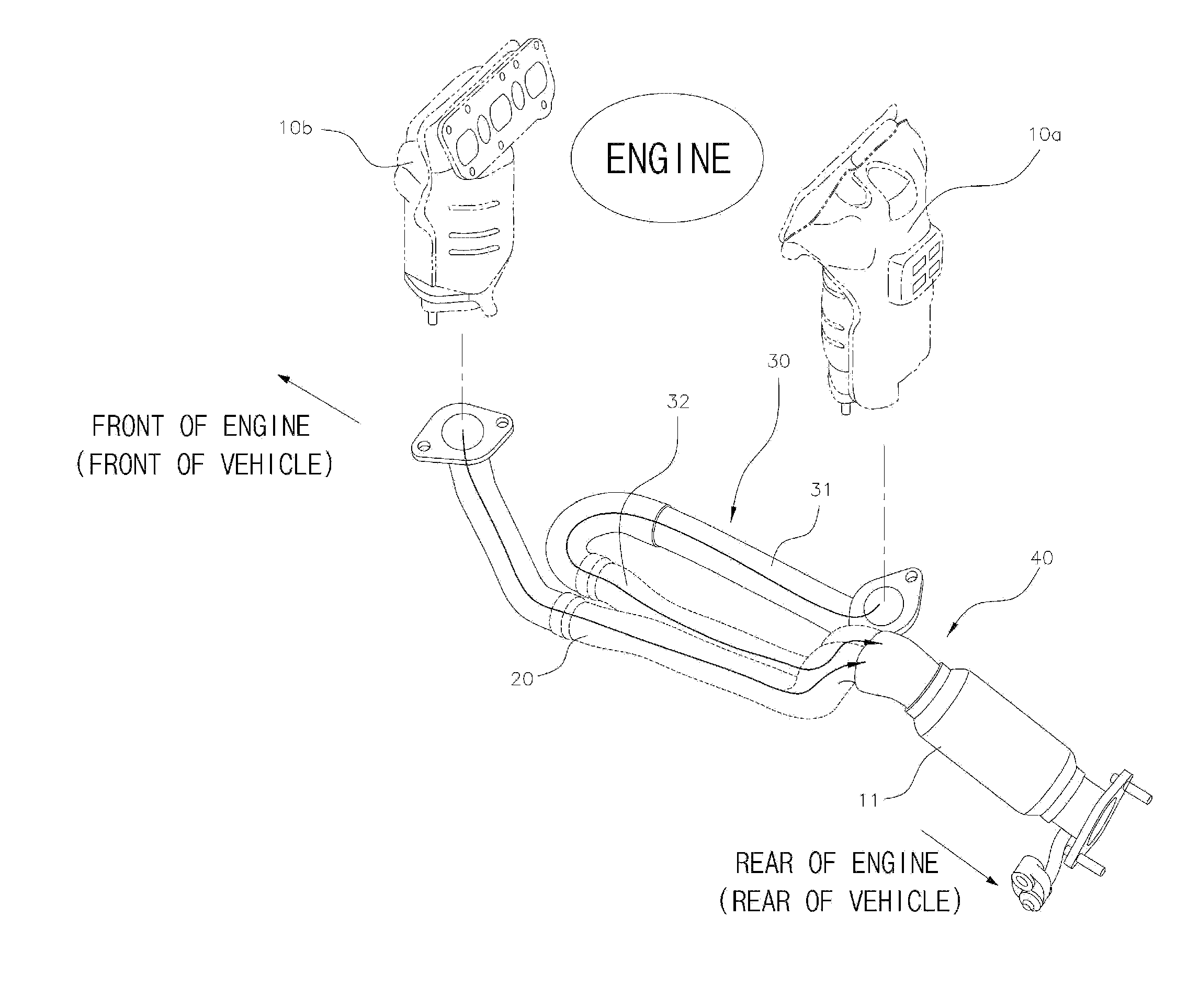
[0034]The structure of an exhaust pipe according to exemplary embodiments of the present invention is described hereafter in more detail with the accompanying drawings.

[0035]Referring to FIG. 2, according to an exemplary exhaust pipe of the present invention, a left manifold 10b is disposed ahead of an engine, i.e., at the front porti...


PUM


Abstract

An exhaust pipe structure of a vehicle having a left manifold disposed in front of an engine and a right manifold disposed behind the engine along a longitudinal direction of the vehicle, which are connected by an underbody catalytic converter, the exhaust pipe structure may include a left exhaust pipe connected to the left manifold and extending toward the rear of the engine, a right exhaust pipe having a straight portion connected to the right manifold and extending toward the front of the engine and a curved portion bending from the straight portion toward the rear of the engine, and a conjunction, one end of which is connected to and communicates with the end of the curved portion of the right exhaust pipe and the end of the left exhaust pipe and the other end of which is connected to the underbody catalytic converter.

Description

CROSS-REFERENCE TO RELATED APPLICATION[0001]The present application claims priority to Korean Patent Application No. 10-2009-0116998, filed on Nov. 30, 2009, the entire contents of which is incorporated herein for all purposes by this reference.BACKGROUND OF THE INVENTION[0002]1. Field of the Invention[0003]The present invention relates to a structure of an exhaust pipe system of a vehicle, in more detail, an exhaust pipe structure of a vehicle having exhaust performance improved by improving the structure of an exhaust pipe such that exhaust gas discharged from both sides of an engine smoothly flows without interfering with each other.[0004]2. Description of Related Art[0005]The driving method of vehicles is classified into FF, FR, RR, and 4WD etc., in accordance with the position of the engine and whether the driving shaft is connected to the front wheels or rear wheels.[0006]Although the driving methods each have merits and demerits, in general, the FR (Front engine, Rear wheel d...

Claims


Application Information

Patent Timeline
IPC IPC(8): F01N13/10F01N3/10
CPCB60K13/04F01N13/107F01N13/009F01N13/185F01N2470/10F01N13/1805F01N13/08F01N13/10
Inventor BONG, HA-DONGLEE, SANG-ILAN, HO-CHANHAN, YOUNG-HOHWANG, IL-JOONGCHAE, SUNG-SOOHAN, HAK-SON
Owner HYUNDAI MOTOR CO LTD
Learn More