Reactive planar suspension for a wheel

a planar suspension and wheel technology, applied in the field of suspension systems, can solve the problems of affecting the overall size and weight of the vehicle, the occupying of existing suspension systems, and the common injury and death of falling over upon hitting an obstacl

Inactive Publication Date: 2011-06-02
MINDMATTER INNOVATES
View PDF11 Cites 42 Cited by
  • Summary
  • Abstract
  • Description
  • Claims
  • Application Information

AI Technical Summary

Benefits of technology

[0005]Accordingly, it is an object of the present invention to provide an improved reactive suspension system that obviates and mitigates from the disadvantages and limitations of the prior art.
[0009]Another objective in a preferred embodiment of the present invention is to provide a suspension system which allows a vehicle to use a harder tire with a lower profile or even eliminates the use of a pneumatic tire altogether without sacrificing comfort or performance.
[0010]Yet another objective in a preferred embodiment of the present invention is to provide a suspension that reduces the unsprung mass of a vehicle.
[0012]The present suspension has significant advantages over prior art suspensions. While conventional suspensions restrict a vehicle's wheel to a fixed travel path, the current suspension allows the vehicle's wheel to travel any two-dimensional path relative to the axle. The wheel travel path of the current suspension is determined by the input, i.e. for any given input, the suspension responds instantaneously or near instantaneously and opposite to the input with a wheel travel path that best responds to the input.
[0013]Since a vehicle's axle is not restricted to a defined travel path, like fixed linear or fixed planar suspensions, the current suspension can react to a new input at any point of a travel path and create a new reactive travel path. Additionally, since the recovery travel of the suspension is not tied to the impact path, the suspension can recover faster than prior art suspensions.

Problems solved by technology

For instance, in wheelchairs, bicycles and motorcycles, injuries and deaths resulting from tipping over upon hitting an obstacle are very common.
Also the existing suspension systems usually take up a significant amount of space that might otherwise be used for passenger comfort, subsystem design modification, or reduction in overall size and weight of the vehicle.
Moreover, the existing suspension systems are difficult to access, making maintenance and repair difficult.
In addition, they are relatively heavy and complex, leading to a negative effect on the vehicle fuel economy.
Finally, the use of pneumatic tires, which is essential in existing suspension systems, results in more rolling resistance thus deteriorating vehicle fuel efficiency.
Pneumatic tires also suffer single point failure which is an obvious safety issue.
However, it is rare that a vehicle only encounters one impact or simple disturbance when traversing an obstacle or “input”.
Rather, a wheel is likely to encounter a series of disturbances like those encountered on a rough road.
The problem with prior art suspensions is that they do not effectively absorb loads resulting from such impacts.

Method used


Image

  • Reactive planar suspension for a wheel
  • Reactive planar suspension for a wheel
  • Reactive planar suspension for a wheel

Examples


Embodiment Construction

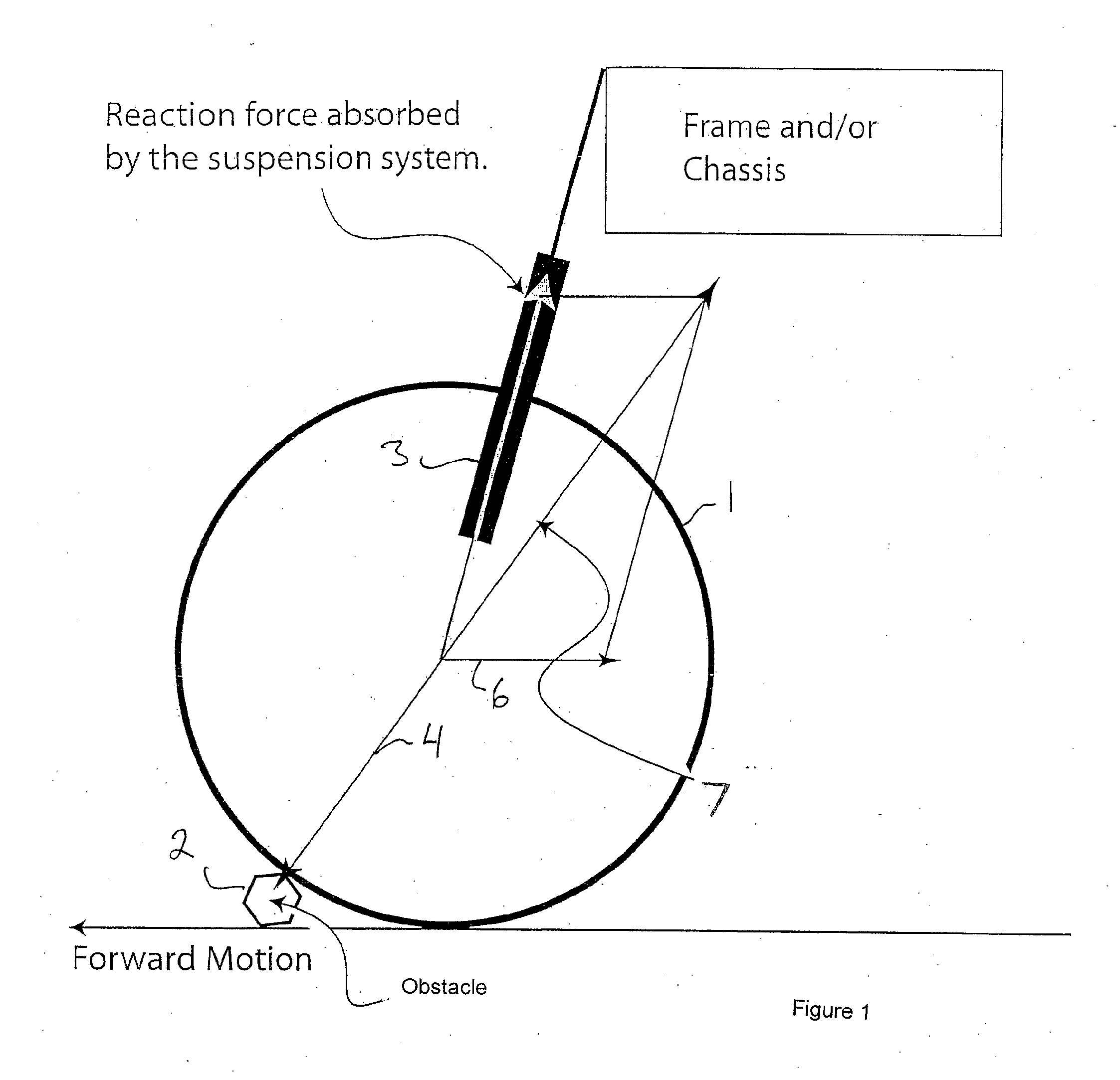
[0049]With reference to FIG. 1, this is a schematical representation of the limitations of current suspensions. Current suspensions are not fully effective at absorbing all of the energy encountered by a wheel contacting an obstacle. As can be seen in the Figure, a wheel 1 encountering an input in the nature of obstruction 2 can move only in the fixed linear or fixed planer path permitted by the suspension. Accordingly, while some of the energy from the impact is absorbed by the suspension's spring and damping mechanism, such as springs and shock absorbers 3, or a combination thereof, a vectored component 7 of the energy is transferred directly to the chassis along the impact's reaction line 4. This is one reason that sharp elevated bumps in the road can feel so jarring compared to relatively larger holes or depressions in the road which deflect the wheel more conformingly in its fixed linear or planer path of travel so that the reaction line is more directly into the shock absorber...


PUM


Abstract

There is described a suspension wheel comprising a substantially rigid rim, a substantially rigid hub disposed concentrically within the rim to define an annular space between the rim and the hub, the hub being adapted for connection to an axle for the wheel, and suspension members disposed in the annular space and connected to the rim and the hub to allow the rim to move in one or both of the horizontal and vertical directions relative to the hub in response to an input to the rim.

Description

FIELD OF THE INVENTION[0001]The present invention relates generally to a suspension system embedded in the wheel of a vehicle or wheeled device such as a bicycle, automobile, wheelchair, hand truck, cart or the like and more particularly to a suspension that resiliently suspends the wheel's axle for any path of independent movement of the wheel relative to the axle in both the X and Z plane within the suspension's limits.BACKGROUND OF THE INVENTION[0002]For any road vehicle, a common method used to isolate undesirable effects of shocks and vibrations is the use of a suspension system. Suspension systems have been traditionally utilized on different types of vehicles, such as motorcycles, passenger cars, trucks and bikes. A suspension is basically a system of a spring and damper that is used to reduce the transferred vibrations to a vehicle's chassis. The spring element can be a coil spring, leaf spring or a torsion bar. The damper element is usually a shock absorber or rubber. Diffe...

Claims


Application Information

Patent Timeline
Patent Type & Authority Applications(United States)
IPC IPC(8): B60B9/10B60B9/02B60B9/04
CPCB60B9/26B60B9/04
Inventor BOYER, GEOFFREYNICOSIA, RAYMOND PAULKHAJEPOUR, ARNIRAZIMI, MOHSEN
Owner MINDMATTER INNOVATES
Why Eureka
Try Eureka