Regenerative thermal energy storage apparatus for an adiabatic compressed air energy storage system

a technology of compressed air energy storage and thermal energy storage, which is applied in the direction of mechanical equipment, indirect heat exchangers, machines/engines, etc., can solve the problems of reducing the heat left in the cavern or other compressed air storage componen

Inactive Publication Date: 2011-06-02
GENERAL ELECTRIC CO
View PDF15 Cites 46 Cited by
  • Summary
  • Abstract
  • Description
  • Claims
  • Application Information

AI Technical Summary

Problems solved by technology

In a diabatic-CAES system, heat generated by the compression train is typically lost to the ambient environment.
That is, the heat of compression may be lost to the ambient in intercoolers and what heat is left when entering the cavern or other compressed air storage component is diminished as the compressed air mixes with the cavern air and further cools to ambient temperature during storage.
Due to this reheating step, the overall efficiency of the diabatic-CAES system is reduced, and the use of natural gas to fuel the combustor leads to carbon emissions and natural resource consumption.
In this way, ACAES systems do not necessitate additional natural gas to reheat the compressed air exiting the cavern or other compressed air storage component.
However, construction of such thick concrete walls leads to substantial engineering difficulties and high costs, thereby reducing the feasibility of implementing an ACAES system as opposed to a less efficient diabatic-CAES system.
Furthermore, high operating temperatures and temperature cycles induce damaging thermal stresses into the concrete walls, and these stresses are amplified as the concrete walls grow thicker.

Method used


Image

  • Regenerative thermal energy storage apparatus for an adiabatic compressed air energy storage system
  • Regenerative thermal energy storage apparatus for an adiabatic compressed air energy storage system
  • Regenerative thermal energy storage apparatus for an adiabatic compressed air energy storage system

Examples


Embodiment Construction

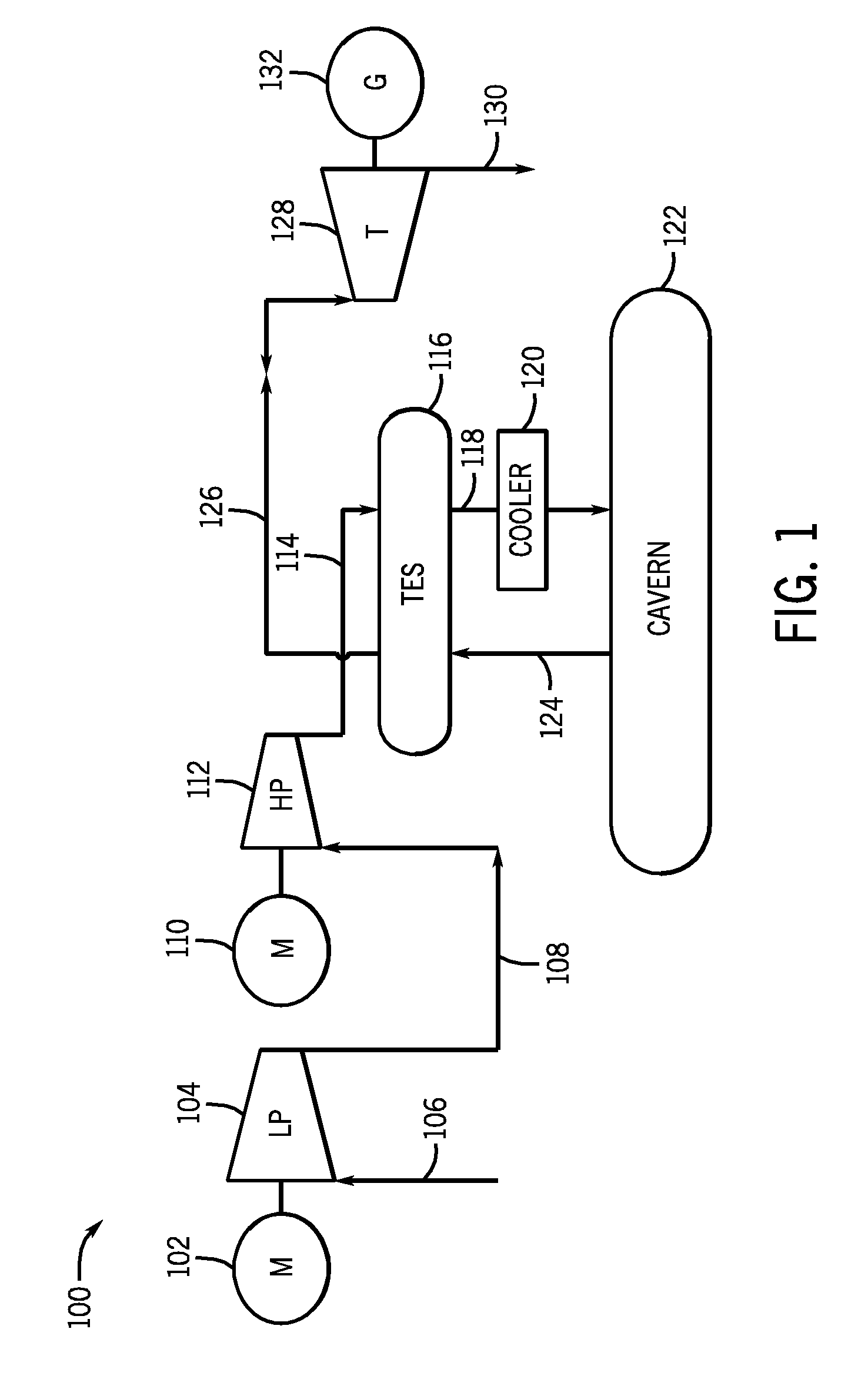
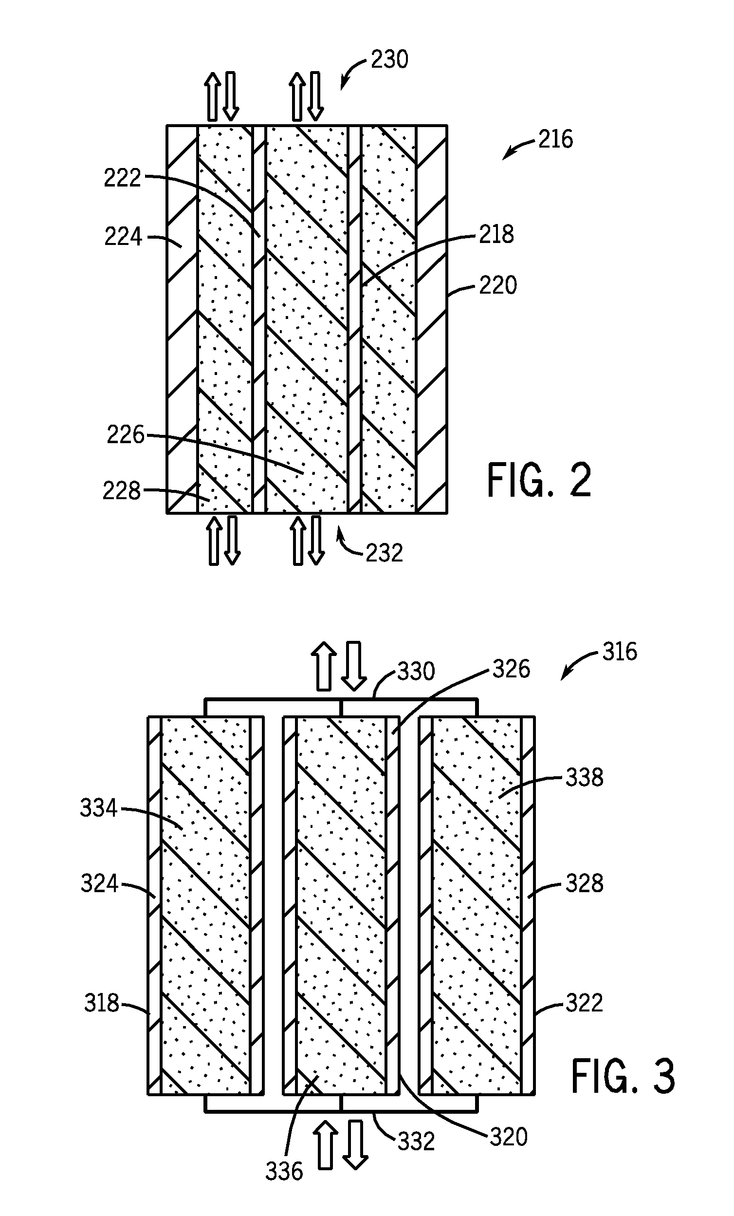
[0021]According to embodiments of the invention, a system is provided that comprises at least one TES unit configured to allow the at least one TES unit to withstand high pressure and temperature fluctuations while maintaining minimal wall thickness.

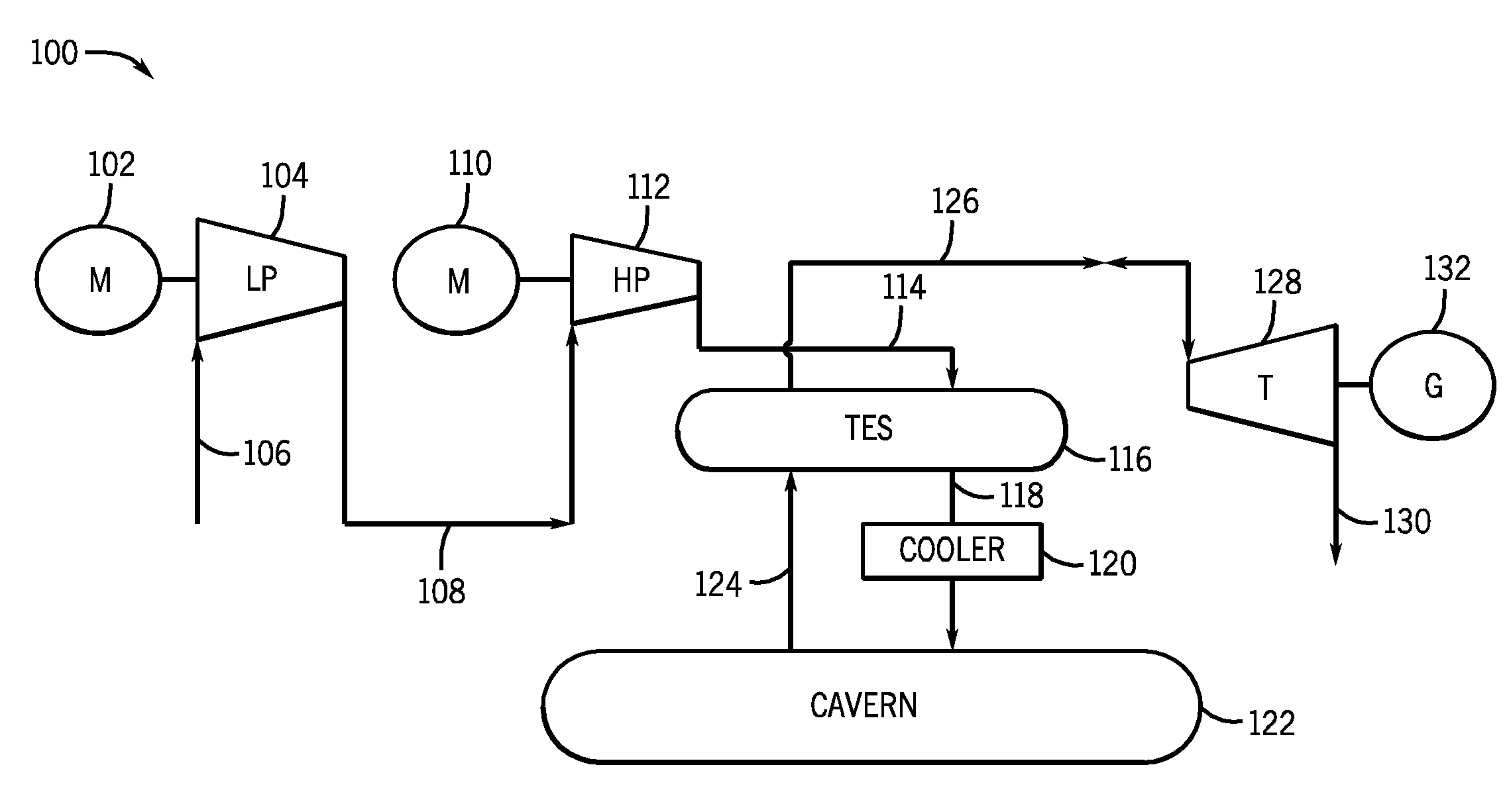
[0022]First, referring to FIG. 1, a schematic arrangement of the primary elements of an ACAES system is shown. ACAES system 100 comprises an electric motor 102 coupled to a low-pressure compressor 104. Electric motor 102 may be electrically powered via conventional means, i.e., the utility grid, during off-peak utility hours. Alternatively, electric motor 102 may be powered by electricity provided via wind farms, solar arrays, or other renewable sources. Electric motor 102 powers low-pressure compressor 104 such that low-pressure compressor 104 pressurizes intake air 106. Pressurized air 108 from low-pressure compressor 104 is then provided to a high-pressure compressor 112 to enable the air to undergo further compression. Similar to low...


PUM


Abstract

A system and method for a thermal energy storage system is disclosed, the thermal energy storage system comprising a plurality of pressure vessels arranged in close proximity to one another, each of the pressure vessels having a wall comprising an outer surface and an inner surface spaced from the outer surface by a respective wall thickness and surrounding an interior volume of the pressure vessel. The interior volume has a first end in fluid communication with one or more compressors and one or more turbines and a second end in fluid communication with at least one of one or more additional compressors, one or more additional turbines, and at least one compressed air storage component. The thermal energy storage system further comprises a thermal storage medium positioned in the interior volume of each of the plurality of pressure vessels.

Description

BACKGROUND OF THE INVENTION[0001]Embodiments of the invention relate generally to compressed air energy storage (CAES) systems and, more particularly, to thermal energy storage (TES) systems in an adiabatic CAES system.[0002]CAES systems allow for the storage of electrical energy without producing substantial emissions and / or consuming vast quantities of natural resources. CAES systems typically include a compression train having one or more compressors. The one or more compressors compress intake air in a compression stage for storage in a cavern, porous rock formation, depleted natural gas / oil field, or other compressed air storage component. The compressed air is then later used to drive turbines to produce electrical energy in an energy generation stage, which can in turn be provided to the utility grid. Often, if utility energy is used to power the compression train during the compression stage, the compression train operates during the off-peak hours of utility plants. The ene...

Claims


Application Information

Patent Timeline
Patent Type & Authority Applications(United States)
IPC IPC(8): F24J3/08
CPCF02C6/16F02C7/10F28D2020/0021F05D2220/60F28D2020/0082Y02E60/15F28D2020/0065Y02E60/16F05D2260/42
Inventor FREUND, SEBASTIAN W.FINKENRATH, MATTHIASBOTERO, CRISTINABELLONI, CLARISSA S.K.GONZALEZ SALAZAR, MIGUEL ANGELHOFFMANN, STEPHANIE MARIE-NOELLE
Owner GENERAL ELECTRIC CO
Why Eureka
Try Eureka