Heat exchanger

a technology of heat exchanger and heat exchanger plate, which is applied in the direction of tubular elements, lighting and heating apparatus, stationary conduit assemblies, etc., and can solve problems such as restrictions that can be problemati

Active Publication Date: 2011-06-02
ABB (SCHWEIZ) AG
View PDF13 Cites 21 Cited by
  • Summary
  • Abstract
  • Description
  • Claims
  • Application Information

AI Technical Summary

Problems solved by technology

Such a restriction can be problematic, because the heat exchanger cannot be installed in an upside down or horizontal position.

Method used


Image

  • Heat exchanger
  • Heat exchanger
  • Heat exchanger

Examples


Embodiment Construction

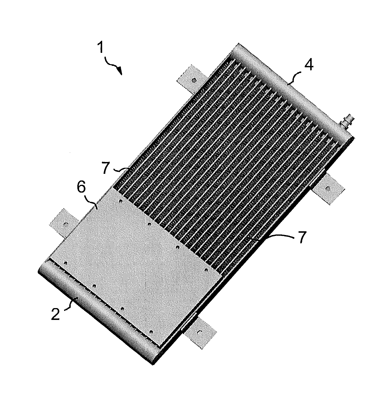
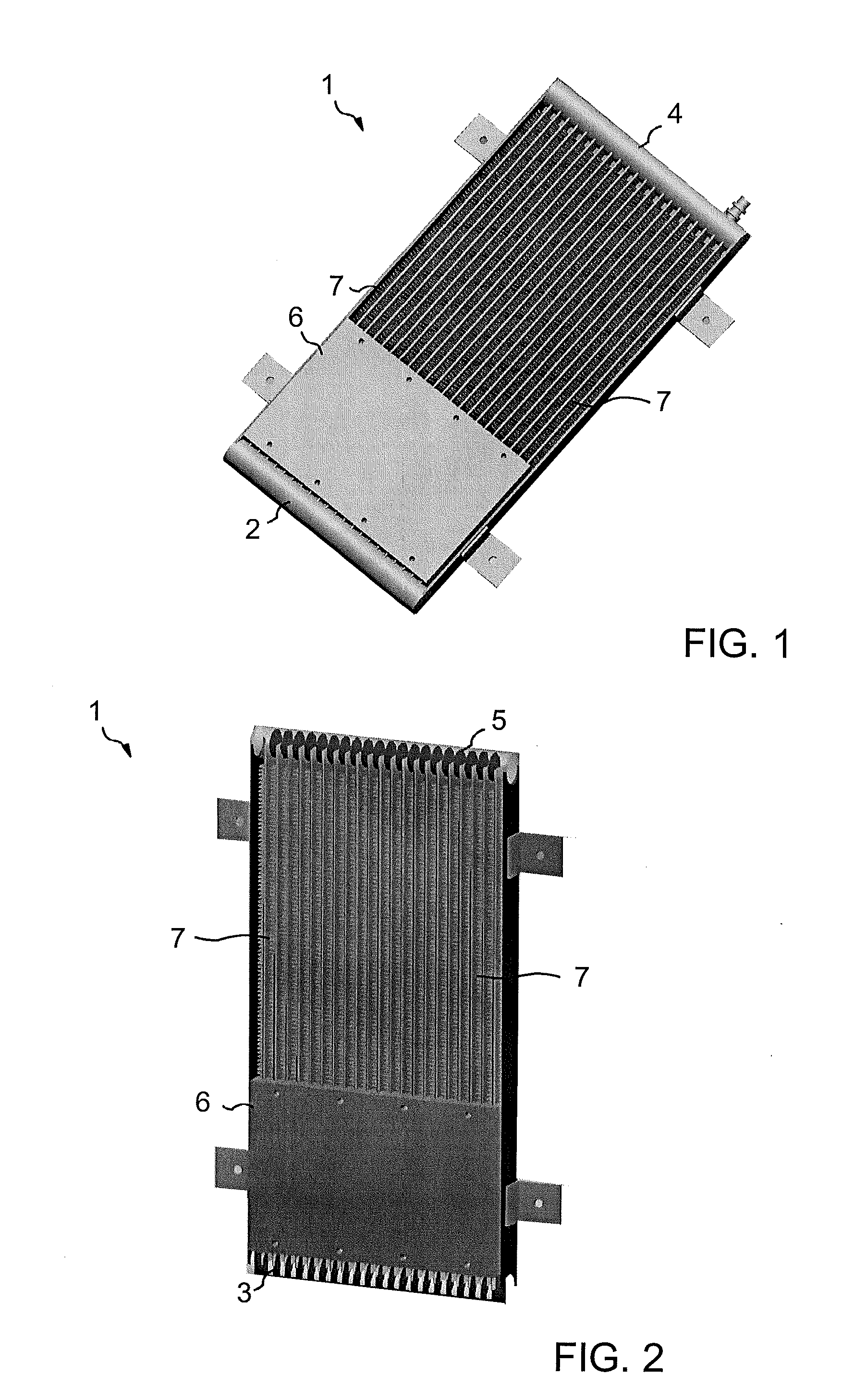
[0018]Exemplary embodiments of a heat exchanger according to the present disclosure need not be installed in a specific position in order to work properly, and can provide a inexpensive and reliable heat exchanger which is less sensitive to the position in which the heat exchanger is installed.

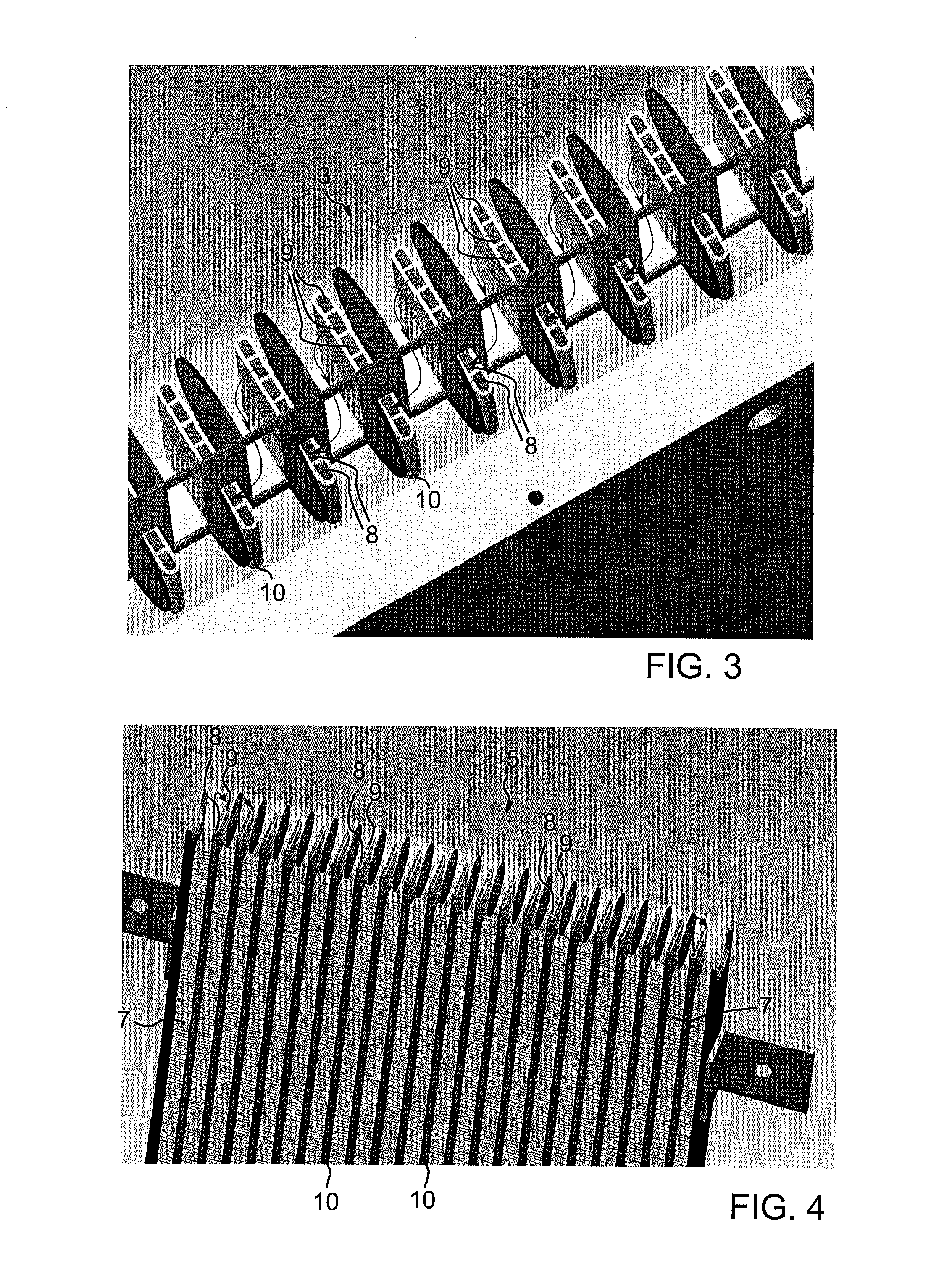
[0019]In accordance with an exemplary embodiment of the disclosure, connecting parts of first and second ends of a heat exchanger can be provided with fluid distribution elements that conduct fluid from predetermined condenser channels to predetermined evaporator channels and vice versa. This arrangement can enable the heat exchanger to work as a Pulsated Heat Pipe (PHP). In such a solution, with condenser channels and evaporator channels having capillary dimensions, oscillations can occur in a small channel loop heat pipe due to the bidirectional expansion of vapour inside the channels. Consequently, the disclosed heat exchanger can work in any orientation, without significant additional cost...


PUM


Abstract

An exemplary heat exchanger includes evaporator channels and condenser channels, connecting parts for providing fluid paths between evaporator channels and the condenser channels, a first heat transfer element for transferring a heat load to a fluid in said evaporator channels, and a second heat transfer element for transferring a heat load from a fluid in the condenser channels. In order to achieve a heat exchanger that can be used in any position, the evaporator channels and said condenser channels can have capillary dimensions. The connecting part arranged at a first end of heat exchanger can include a first fluid distribution element for conducting fluid from a predetermined condenser channel into a corresponding predetermined evaporator channel, and the connecting part arranged at a second end of the heat exchanger can include a second fluid distribution element for conducting fluid from a predetermined evaporator channel into a corresponding predetermined condenser channel.

Description

RELATED APPLICATION[0001]This application claims priority under 35 U.S.C. §119 to European Patent Application No. 09177484.4 in Europe on Nov. 30, 2009, the entire content of which is hereby incorporated by reference in its entirety.FIELD[0002]This disclosure relates to a heat exchanger, such as a heat exchanger suitable for use in cooling electronic apparatuses.BACKGROUND INFORMATION[0003]A heat exchanger in accordance with EP 0231332 A1 includes evaporator channels and condenser channels extending between a first and a second end of the heat exchanger. The opposite ends of the heat exchanger are provided with connecting parts that provide fluid paths between the evaporator channels and the condenser channels. A first heat transfer element is arranged in a vicinity of the first end of the heat exchanger for transferring a heat load to a fluid in said evaporator channels. Similarly, a second heat transfer element is arranged in a vicinity of the second end of the heat exchanger for ...

Claims


Application Information

Patent Timeline
Patent Type & Authority Applications(United States)
IPC IPC(8): F28D15/00
CPCF28D1/05391F28D15/025F28F1/022F28D2015/0225F28D15/0266
Inventor AGOSTINI, BRUNOAGOSTINI, FRANCESCO
Owner ABB (SCHWEIZ) AG
Why Eureka
Try Eureka