Electrode unit and resistance welding device

a technology of electrode unit and resistance welding, which is applied in the direction of resistance electrode holders, electrode features, manufacturing tools, etc., can solve the problems of difficult to apply an even pressure on each of the welding points, complex arrangement, and failure to reduce the size of the entire welder, etc., to achieve simple and compact arrangement

Inactive Publication Date: 2011-06-02
HONDA MOTOR CO LTD
View PDF7 Cites 6 Cited by
  • Summary
  • Abstract
  • Description
  • Claims
  • Application Information

AI Technical Summary

Benefits of technology

[0010]The present invention is made to overcome the above deficiencies. An object of the present invention is to provide an electrode unit having a simple...

Problems solved by technology

Thus, the arrangement becomes complex, thus failing to reduce the size of the entire ...

Method used


Image

  • Electrode unit and resistance welding device
  • Electrode unit and resistance welding device
  • Electrode unit and resistance welding device

Examples


first embodiment

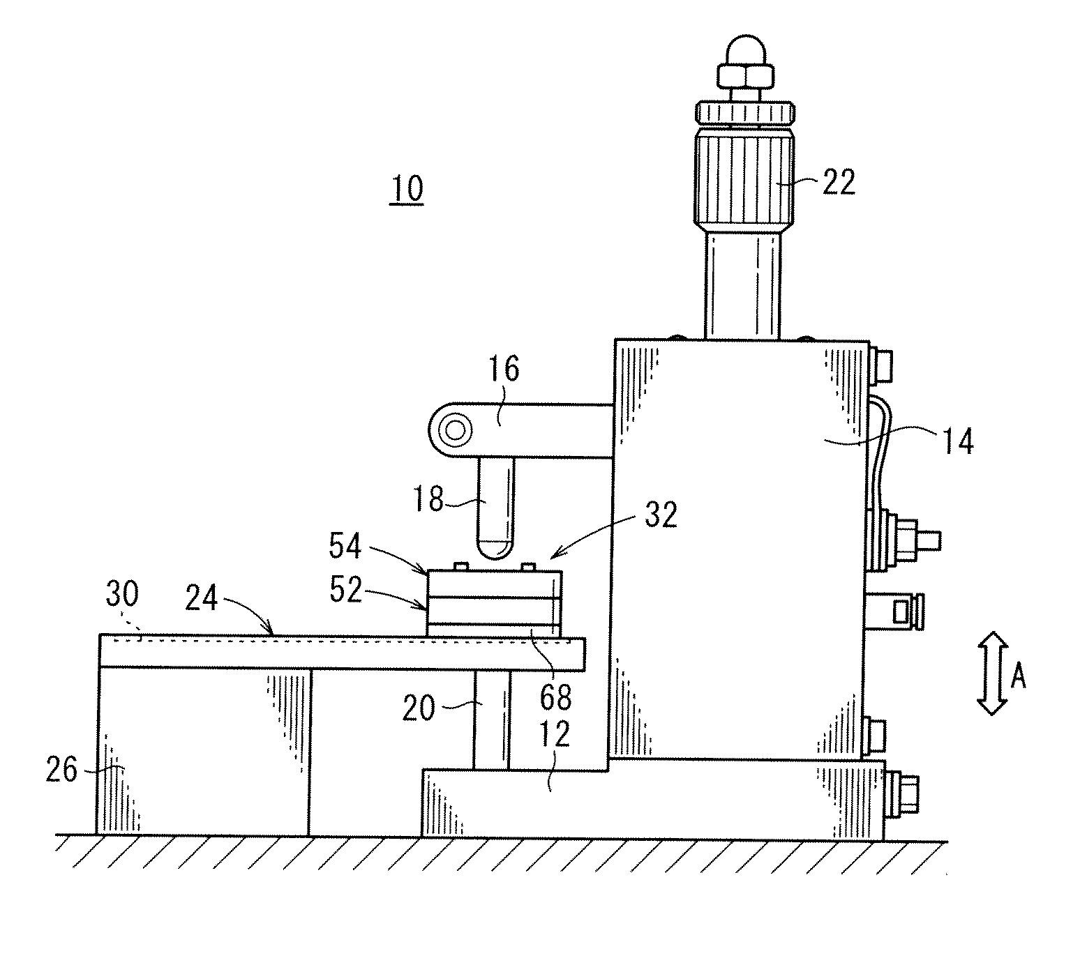
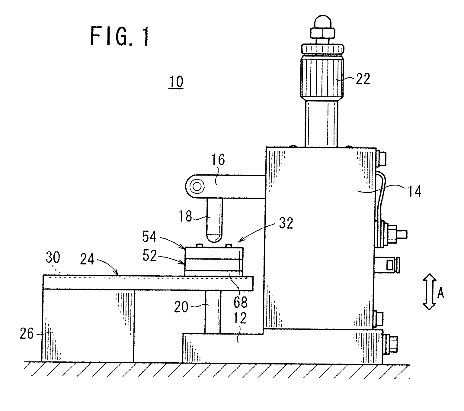
[0029]As shown in FIGS. 1 and 2, a resistance welder 10 according to the present invention includes a base 12 on which a body 14 is mounted. An upper electrode (one of electrodes) 18 is attached to the body 14 via a vertical moving holder 16. A lower electrode 20 is attached to the base 12 so that the lower electrode 20 is coaxially opposed to the upper electrode 18.

[0030]Provided to the body 14 is a pressurizing mechanism 22 for moving the vertical moving holder 16 in a vertical direction (a direction shown by an arrow A) by a manual operation or by an actuator to apply a welding pressure to the upper electrode 18.

[0031]A base plate 24 is placed on the lower electrode 20 and is supported by a backup member 26. The base plate 24 is made of copper or copper alloy such as oxygen-free copper (OFCu) and tough pitch copper (TCu), and is provided with a recess 30 corresponding to a shape of a below-described separator 28. An electrode unit 32 electrically connected with the upper electrod...

third embodiment

[0064]FIG. 10 is a cross section showing a part of an electrode unit 100 according to the present invention.

[0065]The electrode unit 100 includes a first case 102 and a second case 104. The first case 102 and the second case 104 are provided by an electroconductive material such as copper and copper alloy. The stepped holes 56 of the first case 102 receive the electrode pins 58 so that the electrode pins 58 are movable back and forth. A ball plunger 108 serving both as the welding pressure adjusting mechanism and protrusion adjusting mechanism is screwed into a threaded hole 106 provided on a second case 104.

[0066]The ball plunger 108 includes a cylindrical thread 110 screwed to the threaded hole 106, a spring 112 disposed inside the cylindrical thread 110 and a ball 114 disposed at an end of the cylindrical thread 110. The ball 114 touches the head 58b of the electrode pin 58.

[0067]According to the above arrangement, the spring 112 is elastically deformed to adjust the welding pres...


PUM

PropertyMeasurementUnit
Pressureaaaaaaaaaa
Lengthaaaaaaaaaa
Electrical conductoraaaaaaaaaa

Abstract

An electrode unit configuring a resistance welding device is provided with a first chassis section and a second chassis section. A plurality of stepped hole sections are formed in the first chassis section, and an electrode pin is slidably provided in each stepped hole section. On the head section of the electrode pin, a resin ball configuring a welding pressure adjusting mechanism is disposed. In the second chassis section, a screw hole is formed coaxially with each stepped hole section, and a setscrew configuring an extrusion output adjusting mechanism for adjusting an extrusion output of the electrode pin is screwed into each screw hole.

Description

TECHNICAL FIELD[0001]The present invention relates to an electrode unit used for a resistance welder (resistance welding device) having a pair of positive and negative electrodes, the pair of electrodes pressing and energizing a workpiece under pressure to weld the workpiece, and a resistance welder.BACKGROUND ART[0002]Two or more metal pieces that are mutually layered are often bonded by a resistance welding, in which the metal pieces are energized to generate Joule heat to melt the metal pieces while pressing the metal pieces.[0003]A plurality of points have to be welded in order to weld, for instance, a current collecting tab and a current collector of a battery (e.g. a button battery) or terminals of a circuit board. Further, in order to provide a separator of a fuel cell, two or more metal plates are integrally bonded by bonding the metal plates at a plurality of points.[0004]When there are concavity and convexity (e.g. embosses) or steps on a surface of a workpiece in the abov...

Claims


Application Information

Patent Timeline
IPC IPC(8): B23K11/00
CPCB23K11/115B23K2201/36B23K2201/18B23K11/31B23K2101/18B23K2101/36
Inventor KUNICHI, TAKAHIROMORISHITA, YOSHIKIOKIMITSU, TAKEOMIKOSHIDO, AKIHIKOSATO, HIROKIYADORI, TSUYOSHISATO, DAISUKE
Owner HONDA MOTOR CO LTD
Why Eureka
Try Eureka