Methods for laser scribing and separating glass substrates

a technology of laser scribing and glass substrate, which is applied in the direction of glass making apparatus, laser beam welding apparatus, manufacturing tools, etc., can solve the problems of poor edge characteristics, uncontrollable full-body separation rather than the formation of a scribe line,

Inactive Publication Date: 2011-06-02
CORNING INC
View PDF20 Cites 47 Cited by
  • Summary
  • Abstract
  • Description
  • Claims
  • Application Information

AI Technical Summary

Benefits of technology

[0008]In yet another embodiment, a method of separating a glass substrate having a compressive surface layer and an inner tension layer includes forming a defect through the compressive surface layer that is offset from a first edge of the glass substrate. The defect partly exposes the inner tension layer. The method further includes applying a first laser shield to a first shielded region of the glass substrate located between the first edge and the defect and applying a second laser shield to a second shielded region of the glass substrate located between a second edge of the glass substrate and a termination location that is offset from the second edge. The first and second laser shields are operable to prevent the laser beam from being incident on the compressive surface layer in the first and second shielded regions. A scribe line is generated through the compressive surface layer by translating the glass substrate with respect to a laser beam and a cooling jet. The glass substrate may be separated along the scribe line by applying a force to the glass substrate.

Problems solved by technology

However, when the scribe-and-break techniques are utilized to separate strengthened glass such as ion-exchanged glass, uncontrollable full-body separation rather than the formation of a scribe line may occur.
The uncontrolled separation generally leads to poor edge characteristics compared to the scribe and break process.

Method used


Image

  • Methods for laser scribing and separating glass substrates
  • Methods for laser scribing and separating glass substrates
  • Methods for laser scribing and separating glass substrates

Examples


example 1

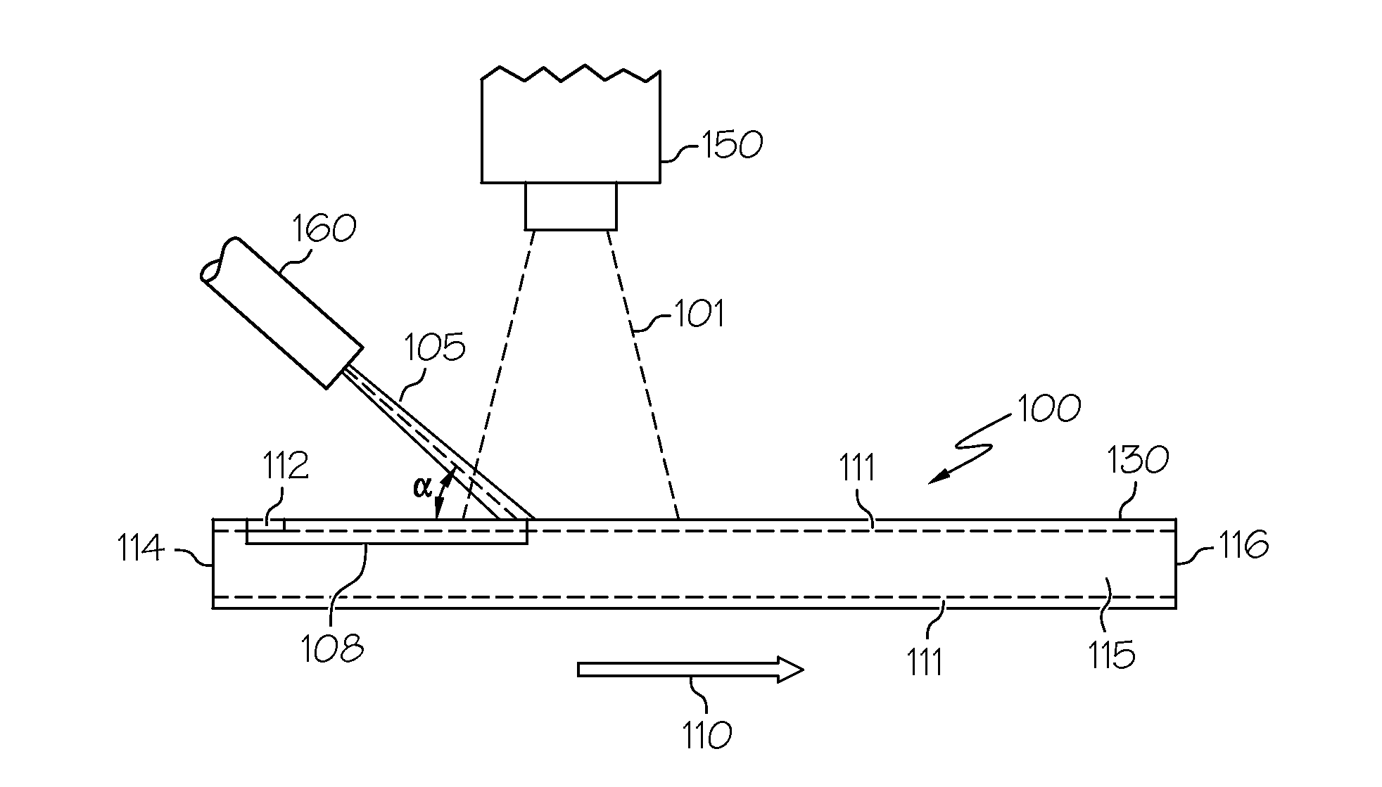
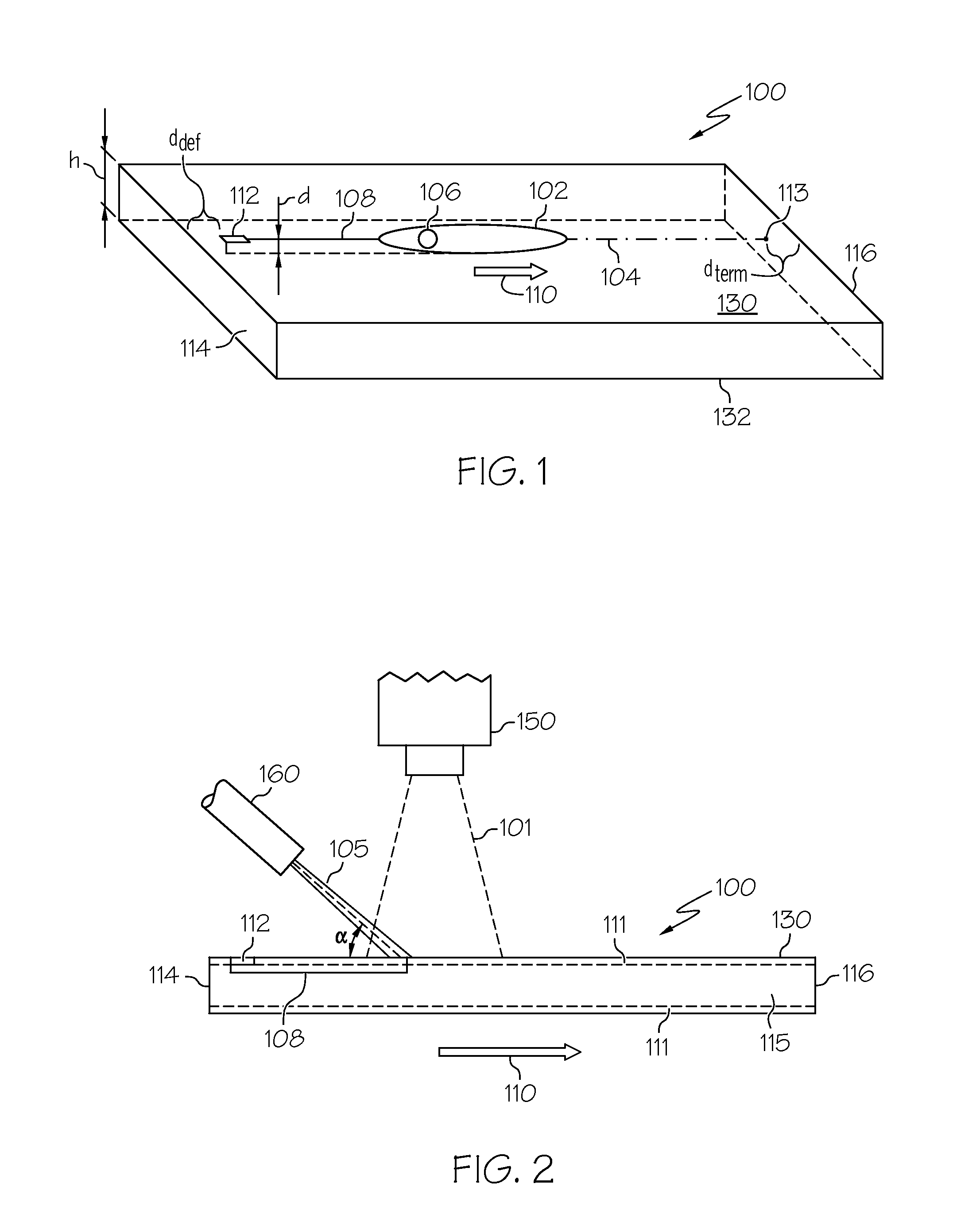
[0048]A fusion drawn, ion-exchanged alkali aluminosilicate glass substrate having a center tension of about 18 MPa, a compressive stress of about 750 MPa, and a depth of layer of about 21 μm was separated by the following method. A defect was created mechanically and was offset approximately 6 mm from the first edge of the glass substrate. Metal strips were used as first and second laser shields to shield the first and second edges of the glass substrate where the laser and water jet passes. The shielded regions extended approximately 6 mm from the respective edges. The laser and water jet were operated at all times as the glass substrate was translated at a speed of about 140 mm / s. The glass did not separate and a scribe line was successfully formed between the shielded regions (i.e., between the defect and a termination location).

example 2

[0049]A fusion drawn, ion-exchanged alkali aluminosilicate glass substrate having the same properties as Example 1 was separated by the following method. A first defect was created by mechanical means on a first edge of the glass substrate. The first defect was offset approximately 8 mm from the first edge. A second defect was created by mechanical means on a second edge of the glass substrate that was adjacent to the first edge. The second defect was offset approximately 8 mm from the second edge. The same process as described in Example 1 was used to generate two separate scribe lines that intersected at a 90° angle. The scribe lines extended between the shielded regions but did not extend to the edges of the glass substrate. The glass did not separate and scribe lines were successfully formed.

example 3

[0050]A fusion drawn, ion-exchanged alkali aluminosilicate glass substrate having a center tension of about 28 MPa, a compressive stress of about 725 MPa and a depth of layer of about 40 μm was separated by the following method. Two pieces of metal were used as first and second laser shields to shield the glass on both edges of the glass substrate where the laser and water jet passes. The distances of the shielded glass (i.e., shielded regions) to the edges were approximately 6 mm. The laser and water jet were operated at all times as the glass substrate was translated at a speed of about 105 mm / s. A successful laser scribing process was observed. The scribe line extended between the two shielded regions and withstood handling after the scribing process.

[0051]It should now be understood that the methods described herein may be used to separate glass substrates such as glass substrates made from borosilicate glasses, as well as glass substrates formed from aluminosilicate glasses inc...


PUM


Abstract

A method of forming a scribe line in a glass substrate having a compressive surface layer and an inner tension layer includes forming a defect through the compressive surface layer that is offset from a first edge of the glass substrate. The defect extends through the compressive surface layer to partially expose the inner tension layer. A scribe line is generated through the compressive surface layer by translating the glass substrate with respect to a laser beam and a cooling jet. The scribe line is initiated at the defect and is terminated at a termination location along the scribe line that is offset from a second edge of the glass substrate.

Description

BACKGROUND[0001]1. Field[0002]The present specification generally relates to methods for separating glass substrates and, more specifically, to methods for forming scribe lines to separate glass substrates.[0003]2. Technical Background[0004]Thin glass substrates have a variety of applications in consumer electronic devices. For example, glass substrates may be used as cover sheets for LCD and LED displays incorporated in mobile telephones, display devices such as televisions and computer monitors and various other electronic devices. Cover sheets used in such devices may be formed by sectioning or separating a large glass substrate into a plurality of smaller glass substrates using various laser cutting techniques. For example, glass substrates may be separated by scribe-and-break techniques. However, when the scribe-and-break techniques are utilized to separate strengthened glass such as ion-exchanged glass, uncontrollable full-body separation rather than the formation of a scribe ...

Claims


Application Information

Patent Timeline
Patent Type & Authority Applications(United States)
IPC IPC(8): B23K26/00
CPCC03B33/091
Inventor LI, XINGHUA
Owner CORNING INC
Why Eureka
Try Eureka