Occupancy-based demand controlled ventilation system

a demand-controlled ventilation and occupancy-based technology, applied in ventilation systems, heating types, static/dynamic balance measurement, etc., can solve the problems of inability to automatically adjust ventilation rates based on occupancy, inability to meet the requirements of occupancy-based demand-controlled ventilation, and inability to meet occupancy-based demand-controlled ventilation. , to achieve the effect of significant energy efficiencies, low cost and simple implementation

Active Publication Date: 2011-06-02
AIKEN THOMAS DAVID
View PDF10 Cites 49 Cited by
  • Summary
  • Abstract
  • Description
  • Claims
  • Application Information

AI Technical Summary

Benefits of technology

[0028]Consequently, the present invention affords significant energy efficiencies not enabled by the prior art in this field. Moreover, this system is relatively inexpensive and simple to implement, unlike systems requiring CO2 monitoring and / or sophisticated active tags.

Problems solved by technology

But these CO2-based systems have several disadvantages, including the reliability and accuracy of the CO2 monitors and the costs associated with installing and maintaining them.
But none of the prior art systems has the capability of automatically adjusting ventilation rates based on detected occupancy levels.
This system is not designed to address occupancy-based demand-controlled ventilation (DCV) and is not adaptable to that purpose.
The Stortoni system requires expensive and bulky active RFID tags having substantial internal data content which serve no purpose in the DCV context.
Therefore, the function of automatically setting ventilation levels in areas based on RFID-detected occupancy is not addressed.
While automatic HVAC control is featured, it is not demand-controlled based on an occupancy count.
Combining these two types of systems is problematic, since the former require sophisticated active tags, while the latter uses simple passive tags.
Even if they could be combined, however, the resulting system would still lack a means of compiling the occupancy data by ventilation zones and converting the compiled zonal data into ventilation control parameters.

Method used


Image

  • Occupancy-based demand controlled ventilation system
  • Occupancy-based demand controlled ventilation system
  • Occupancy-based demand controlled ventilation system

Examples


Embodiment Construction

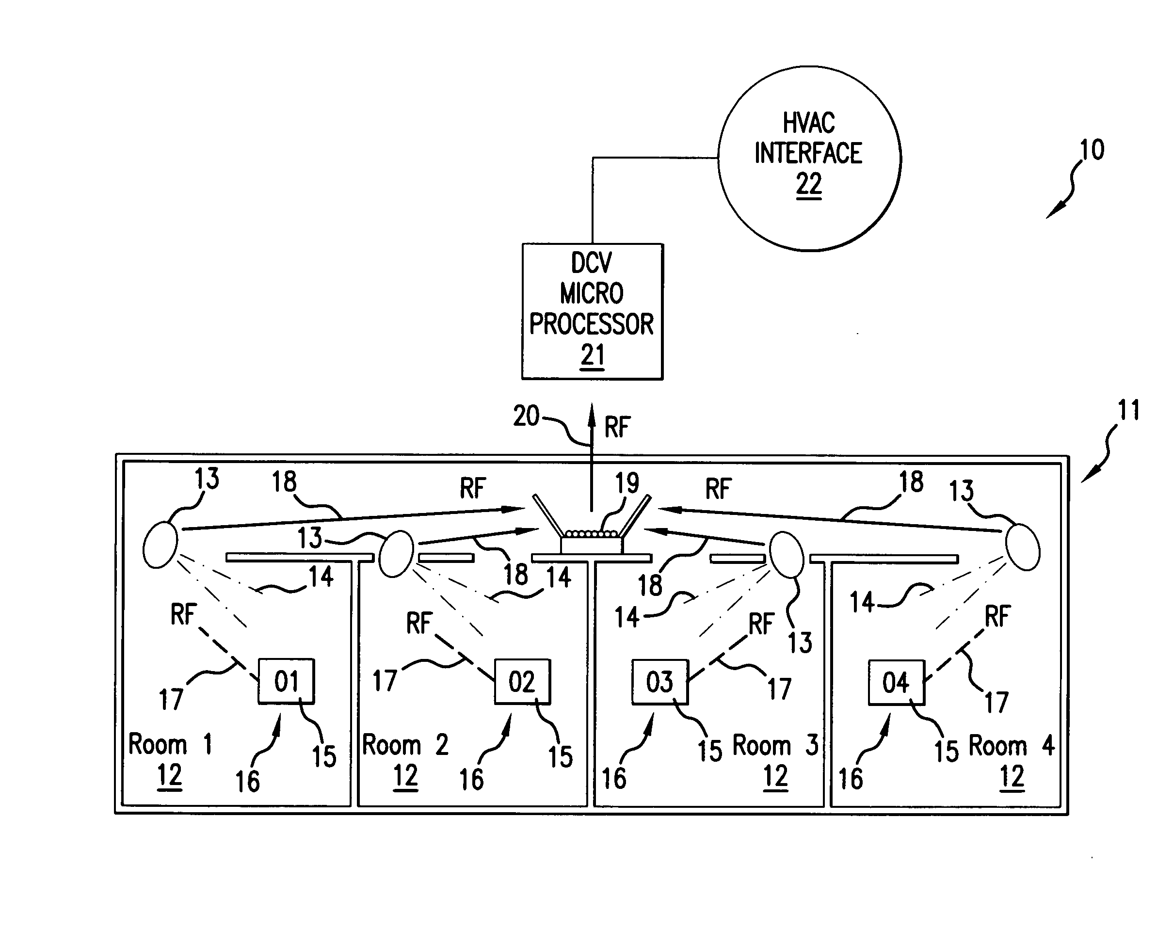
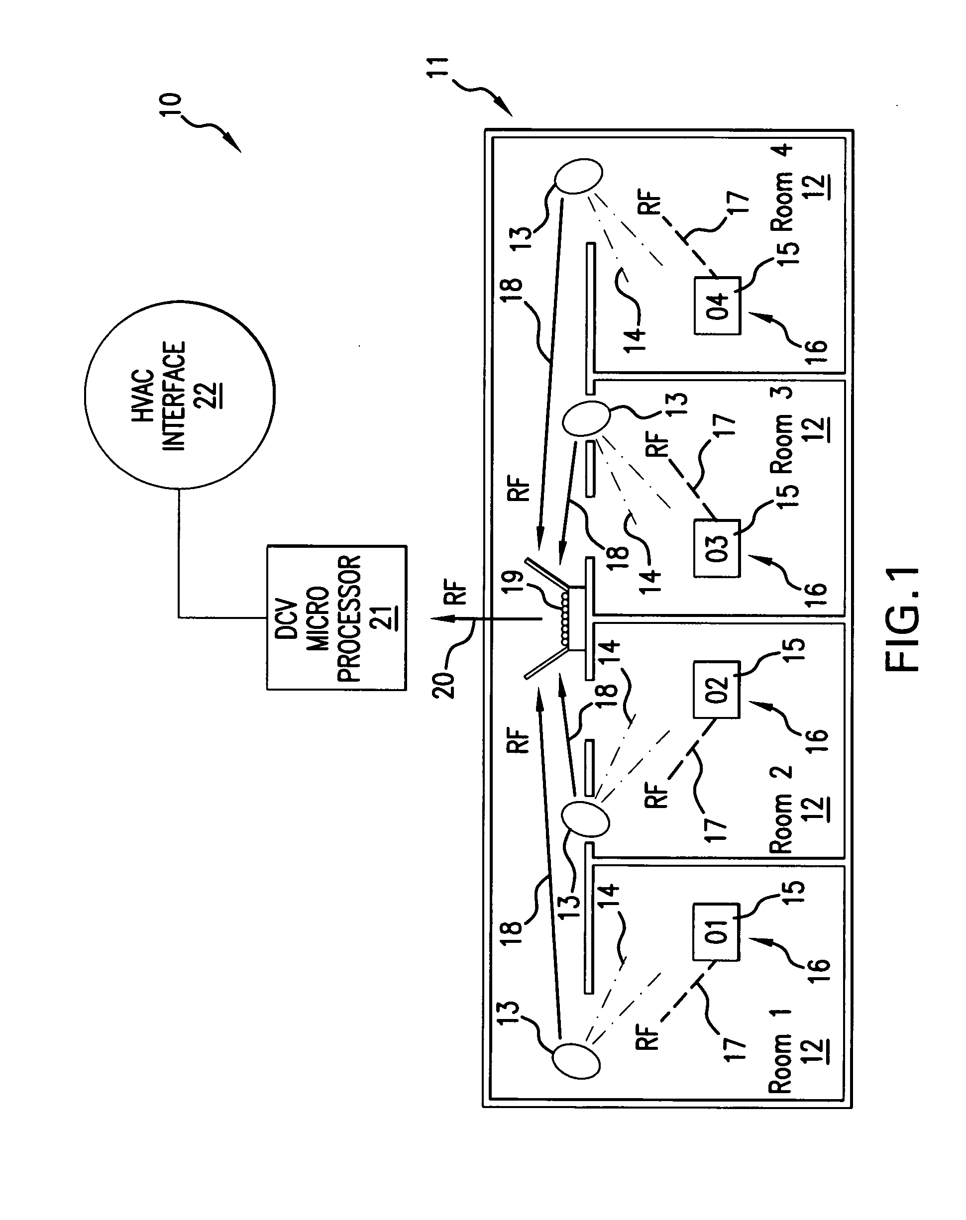
[0034]FIG. 1 depicts a schematic apparatus configuration of the first preferred embodiment of the present invention 10, which uses passive tags. For illustrative purposes, this figure focuses on one ventilation zone 11 of a building that has multiple ventilation zones. The same basic apparatus configuration would be replicated in the other ventilation zones of the building. The exemplary ventilation zone 11 comprises four rooms 12, which are labeled Rooms 1-4. Obviously, depending on the floor plan and ventilation system of the building, each ventilation zone 11 can have more or fewer rooms 12 than are depicted in this figure. Hence, the number of rooms 12 indicated here is for illustrative purposes only.

[0035]In each room 12, there are one or more detectors that are tag readers 13. Preferably, there is one tag reader 13 per room 12, but multiple tag readers 13 may be required for rooms that are very large and / or have very complex configurations. In the preferred embodiment 10, the ...


PUM


Abstract

In a demand control ventilation (DCV) system, ID codes of tags worn by occupants are detected in each room by a tag detector and wirelessly communicated to a zonal occupancy compiler. The zonal occupancy count arrived at by the compiler is transmitted to a DCV microprocessor, which interfaces with the ventilation controller of the building's HVAC system and sets the zonal ventilation rate based on the occupancy count and applicable ASHRAE standards.

Description

BACKGROUND OF THE INVENTION[0001]The present invention relates to the field of HVAC systems and more particularly to the field of ventilation systems for buildings. The present invention specifically addresses demand-controlled ventilation (DCV) systems, in which the ventilation rate is determined based on actual occupancy levels in the ventilated zones, rather than default occupancy levels.[0002]Both environmental and economic concerns in recent years have driven a move toward conserving energy by adjusting the rate of ventilation in various zones of a building to the actual demand for ventilation based on occupancy of the zone. ASHRAE ventilation standards now provide algorithms for adjusting ventilation rates based on occupancy in order to reduce energy consumption when demand falls below default levels. Systems have been developed that estimate occupancy based on levels of carbon dioxide measured in the ventilated space. But these CO2-based systems have several disadvantages, in...

Claims


Application Information

Patent Timeline
Patent Type & Authority Applications(United States)
IPC IPC(8): F24F7/00G05B15/00
CPCF24F11/0001G05B15/02F24F11/0034F24F11/30F24F2120/10F24F11/46F24F11/63F24F11/74
Inventor AIKEN, THOMAS D.
Owner AIKEN THOMAS DAVID
Why Eureka
Try Eureka