Supercharge Your Innovation With Domain-Expert AI Agents!

Wireless power system with selectable control channel protocols

a control channel and wireless power technology, applied in the field of power conversion, can solve the problems of compatibility issues between different vendors' wireless power products, and the device itself cannot be wirelessly powered

Active Publication Date: 2011-06-02
KONINKLJIJKE PHILIPS NV
View PDF8 Cites 149 Cited by
  • Summary
  • Abstract
  • Description
  • Claims
  • Application Information

AI Technical Summary

Problems solved by technology

Thus, the device itself cannot be wirelessly powered without the receive unit coupled to it.
While the above referenced standards organization are attempting to establish standards regarding the control channel protocol, currently, vendors are free to use whatever protocol they chose, making compatibility issues between different vendors' wireless power products.

Method used


Image

  • Wireless power system with selectable control channel protocols
  • Wireless power system with selectable control channel protocols
  • Wireless power system with selectable control channel protocols

Examples


Embodiment Construction

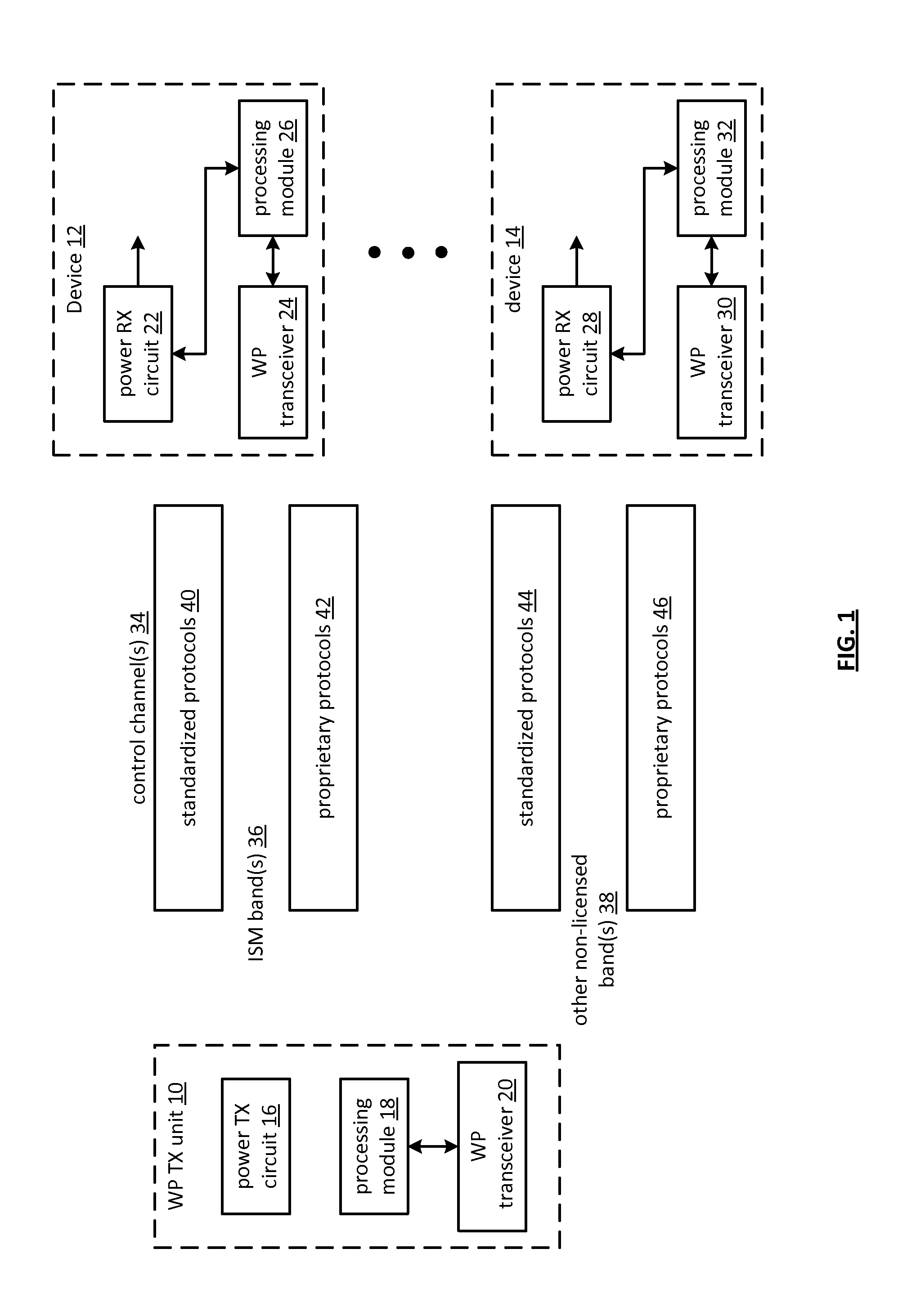
[0048]FIG. 1 is a schematic block diagram of an embodiment of a wireless power system that includes a wireless power (WP) transmit (TX) unit 10 and one or more devices 12-14. The WP TX unit 10 includes a processing module 18, a WP transceiver 20, and a power TX circuit 16. Each device 12-14 includes a WP receive (RX) circuit 22, 28, a processing module 26, 32, and a WP transceiver 24, 30. The device 12-14 will most likely include a plurality of other components depending on its desired functionality. For example, the device 12-14 may be a cell phone, a personal audio / video player, a video game unit, a toy, etc. and includes the corresponding circuitry.

[0049]The processing modules 18, 26, 32 of the WP TX unit 10 and in each of the devices 12-14 may each be a single processing device or a plurality of processing devices. Such a processing device may be a microprocessor, micro-controller, digital signal processor, microcomputer, central processing unit, field programmable gate array, p...


PUM


Abstract

A wireless power system includes a wireless power transmit and receive units. The wireless power transmit unit includes a wireless power transmit circuit that generates a wireless power magnetic field and a transmit unit transceiver that transceives a communication regarding the wireless power magnetic field in accordance with a control channel protocol. The wireless power receive unit includes a wireless power receive circuit, a transceiver, and a processing module. The wireless power receive circuit converts the wireless power magnetic field into a voltage. The receive unit processing module is operable to: identify the control channel protocol; determine whether the receive unit transceiver is capable of communication using the control channel protocol; and, when the receive unit transceiver is capable of communication using the control channel protocol, coordinate configuration of the receive unit transceiver to transceive the communication regarding the wireless power magnetic field via the control channel.

Description

[0001]This patent application is claiming priority under 35 USC §119 to a provisionally filed patent application entitled WIRELESS POWER SYSTEMS AND METHODS, having a provisional filing date of Nov. 30, 2009, and a provisional Ser. No. of 61 / 264,925.STATEMENT REGARDING FEDERALLY SPONSORED RESEARCH OR DEVELOPMENT [0002]NOT APPLICABLEINCORPORATION-BY-REFERENCE OF MATERIAL SUBMITTED ON A COMPACT DISC [0003]NOT APPLICABLEBACKGROUND OF THE INVENTION[0004]1. Technical Field of the Invention[0005]This invention relates to power conversion and more particularly to wireless power conversion and supporting communications thereof.[0006]2. Description of Related Art[0007]The concept of wireless power (i.e., powering a device without an electrical power cord) has been around for a while and has recently been commercialized. In addition, there are a couple of on-going standards discussions (WPC—wireless communication alliance and CEA—consumer electronics association) to standardize wireless power...

Claims


Application Information

Patent Timeline
Patent Type & Authority Applications(United States)
IPC IPC(8): H02J17/00
CPCG06K7/10207G06K7/10346G06K19/0701G06K19/0715H04L29/06163H02J17/00H04B5/0037H02J7/025H04L69/18G06K19/0723H02J50/12H02J50/80H04B5/79H02J50/10
Inventor KARAOGUZ, JEYHANWALLEY, JOHNSESHADRI, NAMBIRAJANVAN DER LEE, REINIER
Owner KONINKLJIJKE PHILIPS NV
Features
  • R&D
  • Intellectual Property
  • Life Sciences
  • Materials
  • Tech Scout
  • Unparalleled Data Quality
  • Higher Quality Content
  • 60% Fewer Hallucinations
Learn More