Antenna with superstrate providing high-gain and beam width control

a superstrate and beam width control technology, applied in the field of antennas, can solve the problems of reducing the overall efficiency of the array antenna, affecting the beam width control, and increasing the energy loss of patch antenna feed proportionally, so as to achieve the effect of increasing the gain and beam width control

Inactive Publication Date: 2011-06-02
ELECTRONICS & TELECOMM RES INST
View PDF8 Cites 7 Cited by
  • Summary
  • Abstract
  • Description
  • Claims
  • Application Information

AI Technical Summary

Benefits of technology

[0009]The following description relates to an antenna which can simultaneously achieve increase of gain, beam width control, and high front-to-back ratio (FBR).

Problems solved by technology

However, in an array antenna, as the number of patch antennas increases, energy loss due to patch antenna feed increases proportionally.
Consequently, the overall efficiency of the array antenna is reduced.
However, these methods have difficulties in beam width control.
Furthermore, since a gain of the antenna is maximized when a distance between a superstrate and a ground plane is half-wave, the volume of the antenna is disadvantageously increased.

Method used


Image

  • Antenna with superstrate providing high-gain and beam width control
  • Antenna with superstrate providing high-gain and beam width control
  • Antenna with superstrate providing high-gain and beam width control

Examples


Embodiment Construction

[0021]The following description is provided to assist the reader in gaining a comprehensive understanding of the methods, apparatuses, and / or systems described herein. Accordingly, various changes, modifications, and equivalents of the methods, apparatuses, and / or systems described herein will be suggested to those of ordinary skill in the art. Also, descriptions of well-known functions and constructions may be omitted for increased clarity and conciseness.

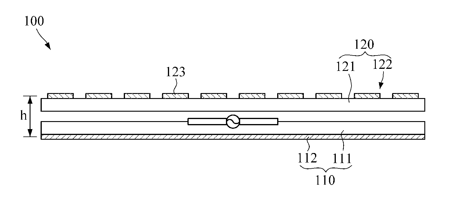
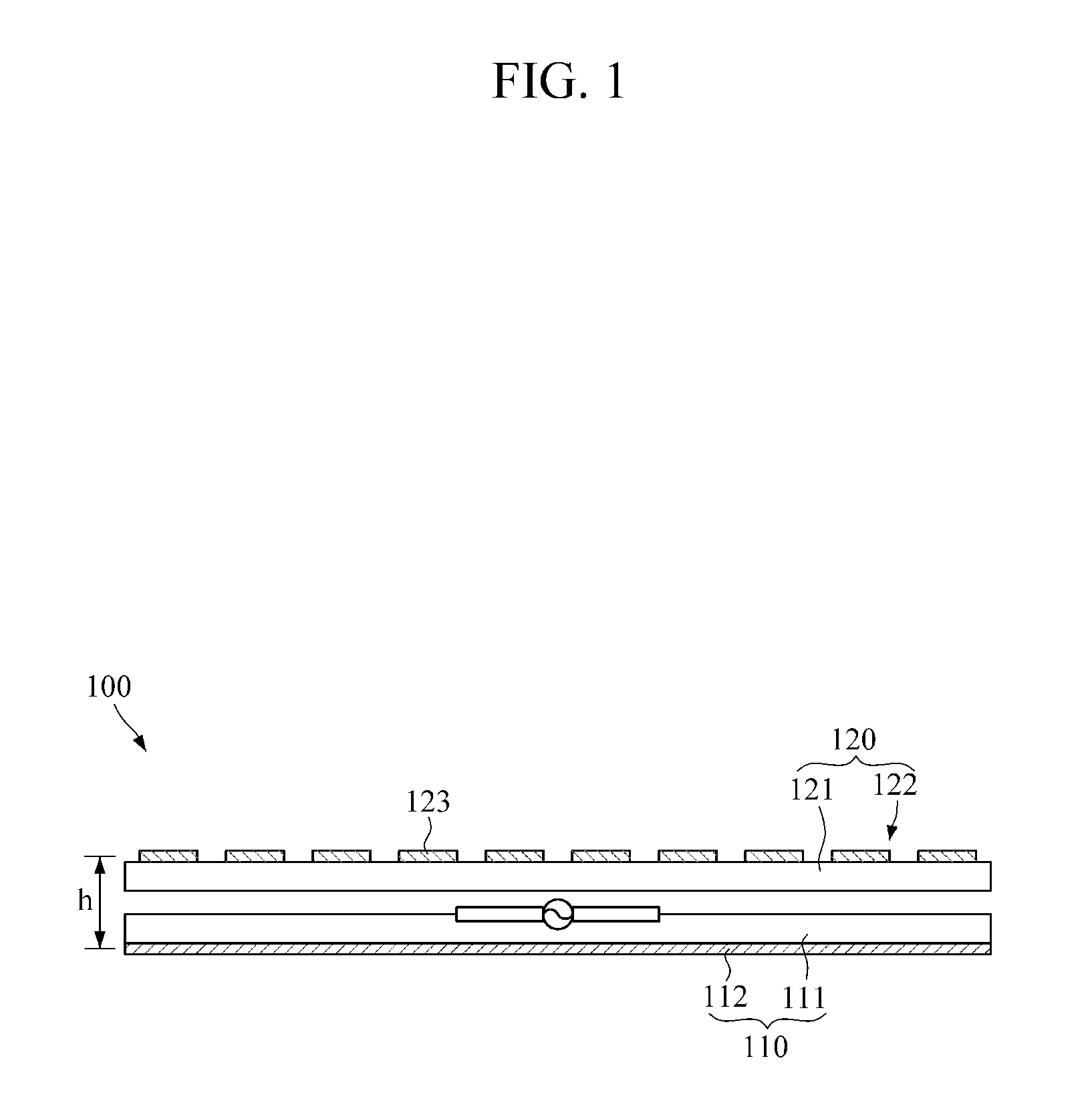
[0022]FIG. 1 illustrates a cross-sectional view of an example of an antenna. FIG. 2 illustrates a cross-sectional view of an example of a unit cell of a superstrate shown in FIG. 1.

[0023]Referring to FIGS. 1 and 2, the antenna 100 includes a feed antenna 110 and the superstrate 120. The feed antenna 110 is to feed power to the antenna 100. The feed antenna 110 may include a dielectric substrate 111 and a ground plane 112. The ground plane 112 is formed on one surface of the dielectric substrate 111.

[0024]The feed antenna 110 may h...


PUM


Abstract

An antenna employed in a base station is provided. The antenna comprises a feed antenna configured to feed power, and a superstrate configured to be located on an upper portion of the feed antenna and have a conductive pattern for increasing a gain and beam width control on a surface of a dielectric substrate. Accordingly, gain increase and beam width control of the antenna can be simultaneously realized.

Description

CROSS-REFERENCE TO RELATED APPLICATION(S)[0001]This application claims the benefit under 35 U.S.C. §119(a) of Korean Patent Application No. 10-2009-0116987, filed on Nov. 30, 2009, the entire disclosure of which is incorporated herein by reference for all purposes.BACKGROUND[0002]1. Field[0003]The following description relates to an antenna which is employed in a base station or the like.[0004]2. Description of the Related Art[0005]Generally, to increase a gain of an antenna of a base station which requires high-gain radiation characteristics and beam width control, an array antenna comprising a number of patch antennas is used.[0006]However, in an array antenna, as the number of patch antennas increases, energy loss due to patch antenna feed increases proportionally. Consequently, the overall efficiency of the array antenna is reduced. Moreover, to obtain an appropriate gain and radiation pattern, an interval between patch antennas and a signal phase fed to the patch antennas shoul...

Claims


Application Information

Patent Timeline
Patent Type & Authority Applications(United States)
IPC IPC(8): H01Q1/38H01Q13/10H01Q13/00H01Q9/16
CPCH01Q1/38H01Q9/0407H01Q19/005H01Q13/00H01Q13/10H01Q9/16H01Q21/00H01Q21/08
Inventor JU, JEONG-HO
Owner ELECTRONICS & TELECOMM RES INST
Why Eureka
Try Eureka