Turbine assemblies with impingement cooling

a technology of turbine assemblies and impingement cooling, which is applied in the direction of liquid fuel engines, vessel construction, marine propulsion, etc., can solve the problems of affecting the demand for cooling flow, affecting the primary function of the engine, and the structure is not as effective as desired

Active Publication Date: 2011-06-02
HONEYWELL INT INC
View PDF17 Cites 26 Cited by
  • Summary
  • Abstract
  • Description
  • Claims
  • Application Information

AI Technical Summary

Benefits of technology

[0009]In accordance with an exemplary embodiment, a gas turbine engine assembly includes a housing including an annular duct wall that at least partially defines a mainstream hot gas flow path configured to receive mainstream hot gas flow; a stator assembly comprising a stator vane extending into the mainstream gas flow; and a turbine rotor assembly upstream of the stator assembly and defining a turbine cavity with the stator assembly. The turbine rotor assembly includes a r...

Problems solved by technology

In addition, the demand for cooling flow may be impacted by an irregular and unpredictable ingestion of mainstream hot gases from the hot gas flow path into the internal engine cavity.
Various attempts to prevent hot gas ingestion between adjacent stator vanes and rotor blades have primarily involved the use of overlapping lip-type structures in close running clearance, often r...

Method used


Image

  • Turbine assemblies with impingement cooling
  • Turbine assemblies with impingement cooling
  • Turbine assemblies with impingement cooling

Examples


Embodiment Construction

[0015]The following detailed description is merely exemplary in nature and is not intended to limit the invention or the application and uses of the invention. Furthermore, there is no intention to be bound by any theory presented in the preceding background or the following detailed description.

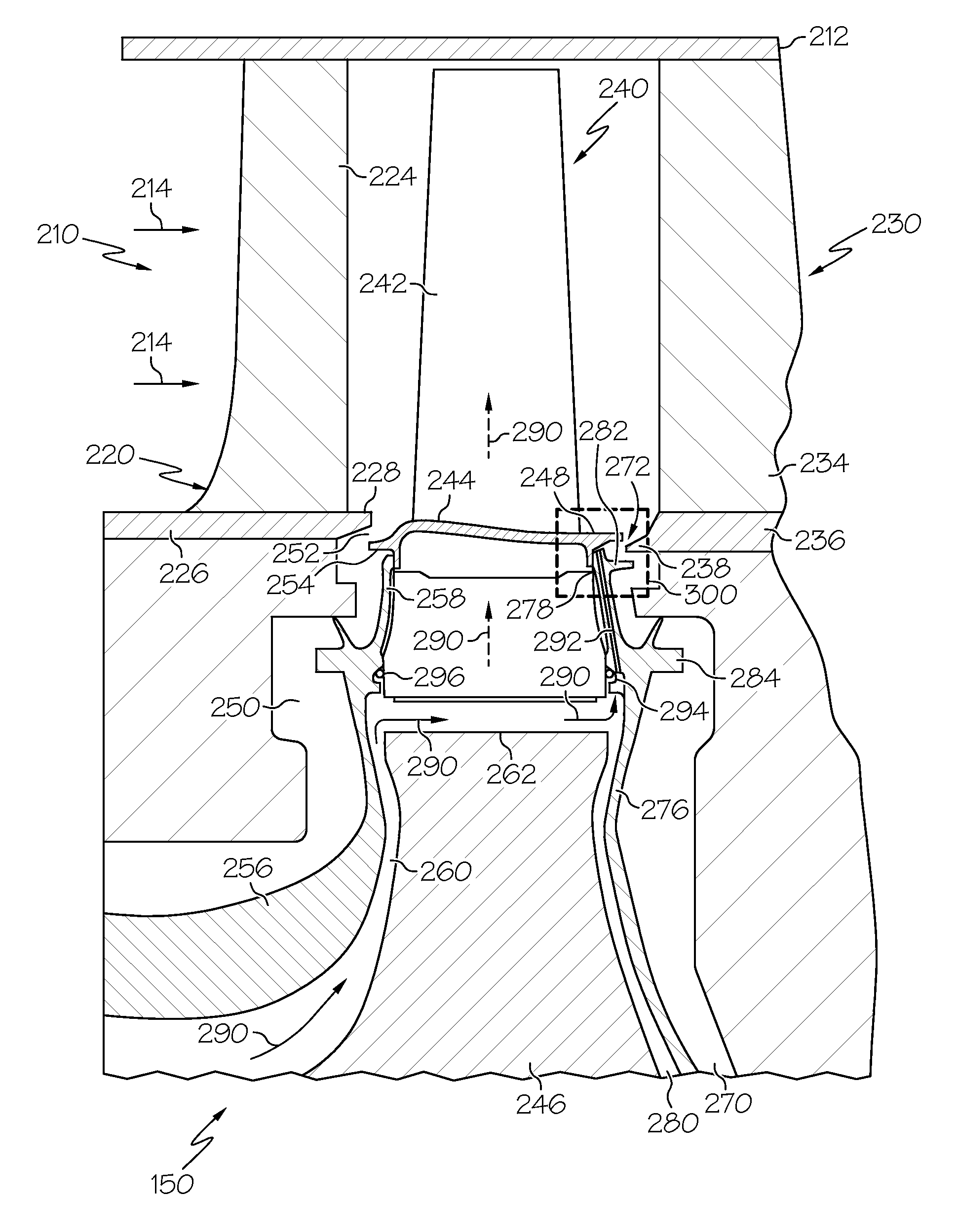
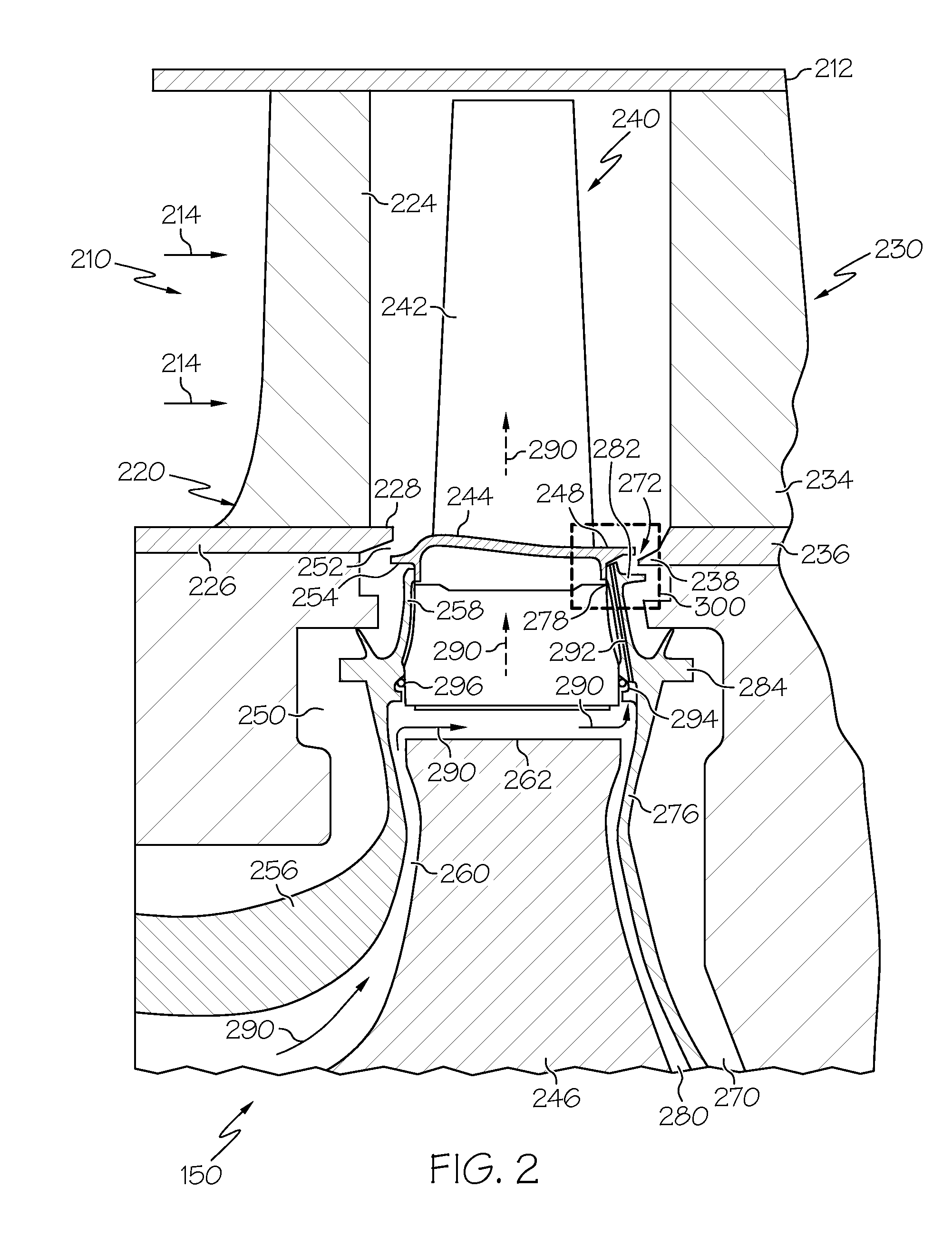
[0016]Broadly, exemplary embodiments discussed herein include gas turbine engine assemblies that maintain suitable temperatures and reduce or eliminate of the effects of hot gas ingestion. More particularly, exemplary gas turbine engine assemblies include a turbine rotor assembly with an aft flow discourager. An aft seal plate may be configured to cooperate with the aft flow discourager to protect the rotor disk components, including the aft flow discourager, from elevated temperatures and conditions. Additionally, the aft seal plate may have channels that deliver impingement cooling flow to the aft flow discourager.

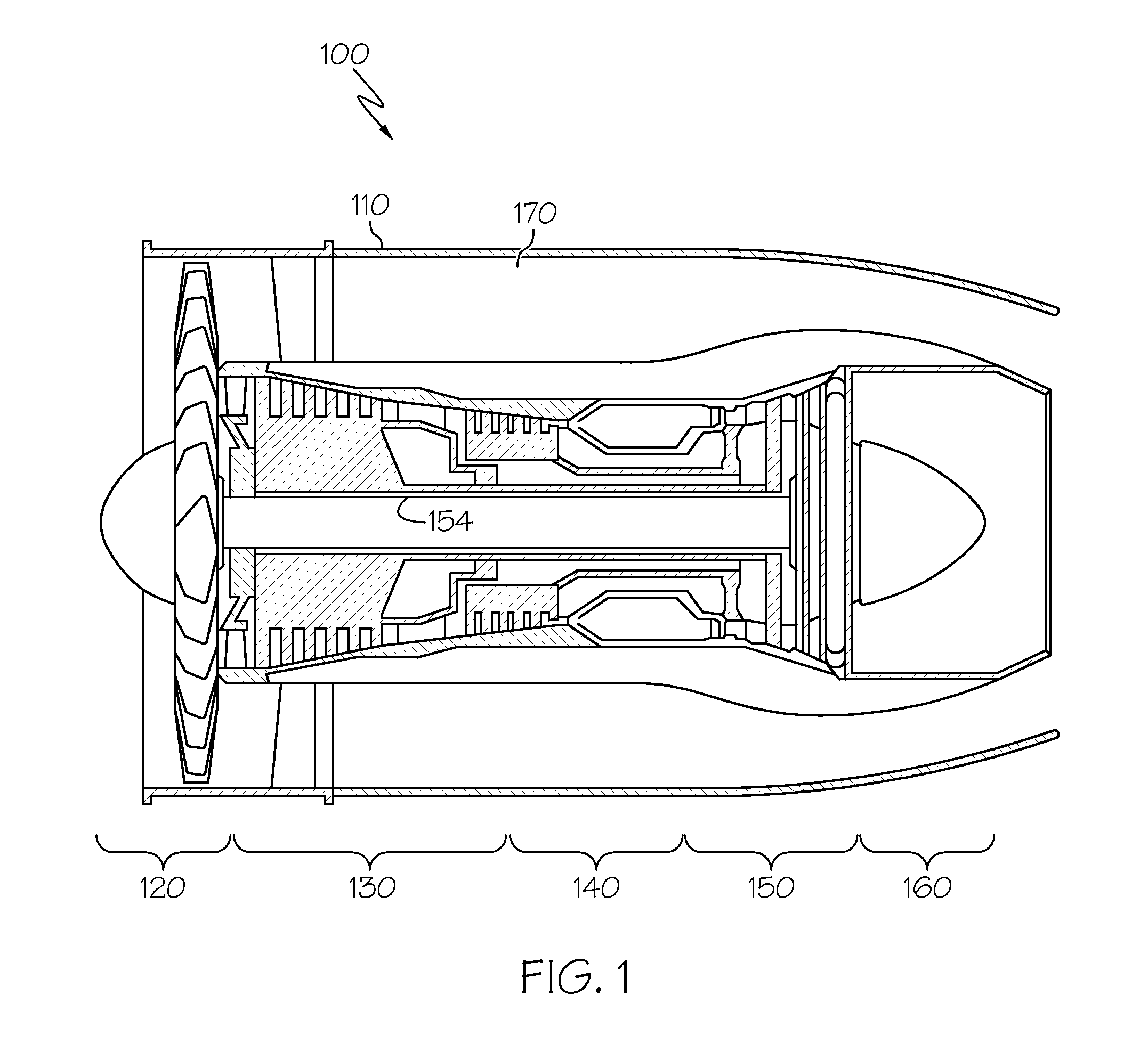
[0017]FIG. 1 is a cross-sectional view of a gas turbine engine 100, accordin...


PUM


Abstract

A gas turbine engine assembly includes a housing including an annular duct wall that at least partially defines a mainstream hot gas flow path; a stator assembly with a stator vane extending into the mainstream gas flow; and a turbine rotor assembly upstream of the stator assembly and defining a turbine cavity with the stator assembly. The turbine rotor assembly includes a rotor disk having a forward side and an aft side, a rotor platform positioned on a periphery of the rotor disk, the rotor platform defining an aft flow discourager, a rotor blade mounted on the rotor platform extending into the mainstream gas flow, and an aft seal plate mounted on the aft side of the rotor disk. The aft seal plate has a radius such that the aft seal plate protects the rotor disk from hot gas ingestion.

Description

STATEMENT REGARDING FEDERALLY SPONSORED RESEARCH OR DEVELOPMENT[0001]This invention was made with Government support under Contract No. W911W6-08-2-0001 awarded by the US Army. The Government has certain rights in this invention.TECHNICAL FIELD[0002]The present invention generally relates to gas turbine engine assemblies, and more particularly relates to turbine assemblies with improved cooling characteristics.BACKGROUND[0003]A gas turbine engine may be used to power various types of vehicles and systems. A particular type of gas turbine engine that may be used to power aircraft is a turbofan gas turbine engine. A turbofan gas turbine engine conventionally includes, for example, five major sections: a fan section, a compressor section, a combustor section, a turbine section, and an exhaust section. The fan section is typically positioned at the inlet section of the engine and includes a fan that induces air from the surrounding environment into the engine and accelerates a fraction ...

Claims


Application Information

Patent Timeline
IPC IPC(8): F01D5/08
CPCF01D5/087F01D5/187F05D2260/201F05D2240/81Y02T50/676Y02T50/60
Inventor SMOKE, JASONTUCKER, BRADLEY REEDMITLIN, BOBCRITES, DANRANA, RAJIVMIRZAMOGHADAM, ALEXANDER
Owner HONEYWELL INT INC
Why Eureka
Try Eureka