Hot sanitary water system and method for disinfection of hot water

a hot water system and hot water technology, applied in specific water treatment objectives, water treatment parameter control, waste water treatment from bathing facilities, etc., can solve the problems of legionella /i>proliferation, high mortality rate of humans, dangerous for human health,

Active Publication Date: 2015-11-19
SANIPUR
View PDF11 Cites 16 Cited by
  • Summary
  • Abstract
  • Description
  • Claims
  • Application Information

AI Technical Summary

Problems solved by technology

The warm water used for hygienic and sanitary, but also for technical, industrial and zoo-technical purposes may harbor microorganisms dangerous to human health, such as Legionella present in warm water and responsible for a bacterial infection, Legionellosis, which can strike humans with a high mortality rate, especially in a hospital setting.
In warm water instead, at temperatures up to about 65° C., Legionella proliferates significantly, reaching concentrations dangerous for human health.
As a result, the warm water for sanitary and technical use, for example in the range from 45° C. to 50° C., in bathrooms, showers, cooling towers, etc. can be a dangerous source of infection by Legionella bacteria.
The application of thermal shock is however limited since hydraulic systems operating discontinuously cannot ensure the temperature limit is reached in remote points, such as in the terminal withdrawal points of the water, where the maximum temperature reached is often lower than 60° C.
However, chlorination involves the formation of chlorinated organic by-products of proven toxicity (THM—trihalomethane chlorinates).
However, chlorine dioxide does not have selective properties and thus also attacks the pipes, especially the latest generation plastic pipes of the plumbing system.
Both methods appear feasible, but have some drawbacks in the control of the concentration of monochloramine and its decomposition by-products, especially the ammonium ions (NH4+).
This exacerbates the problem of variations in the concentration of monochloramine and the excessive accumulation of decomposition by-products, in particular ammonium ions, in the recirculated warm water.

Method used


Image

  • Hot sanitary water system and method for disinfection of hot water
  • Hot sanitary water system and method for disinfection of hot water
  • Hot sanitary water system and method for disinfection of hot water

Examples


Embodiment Construction

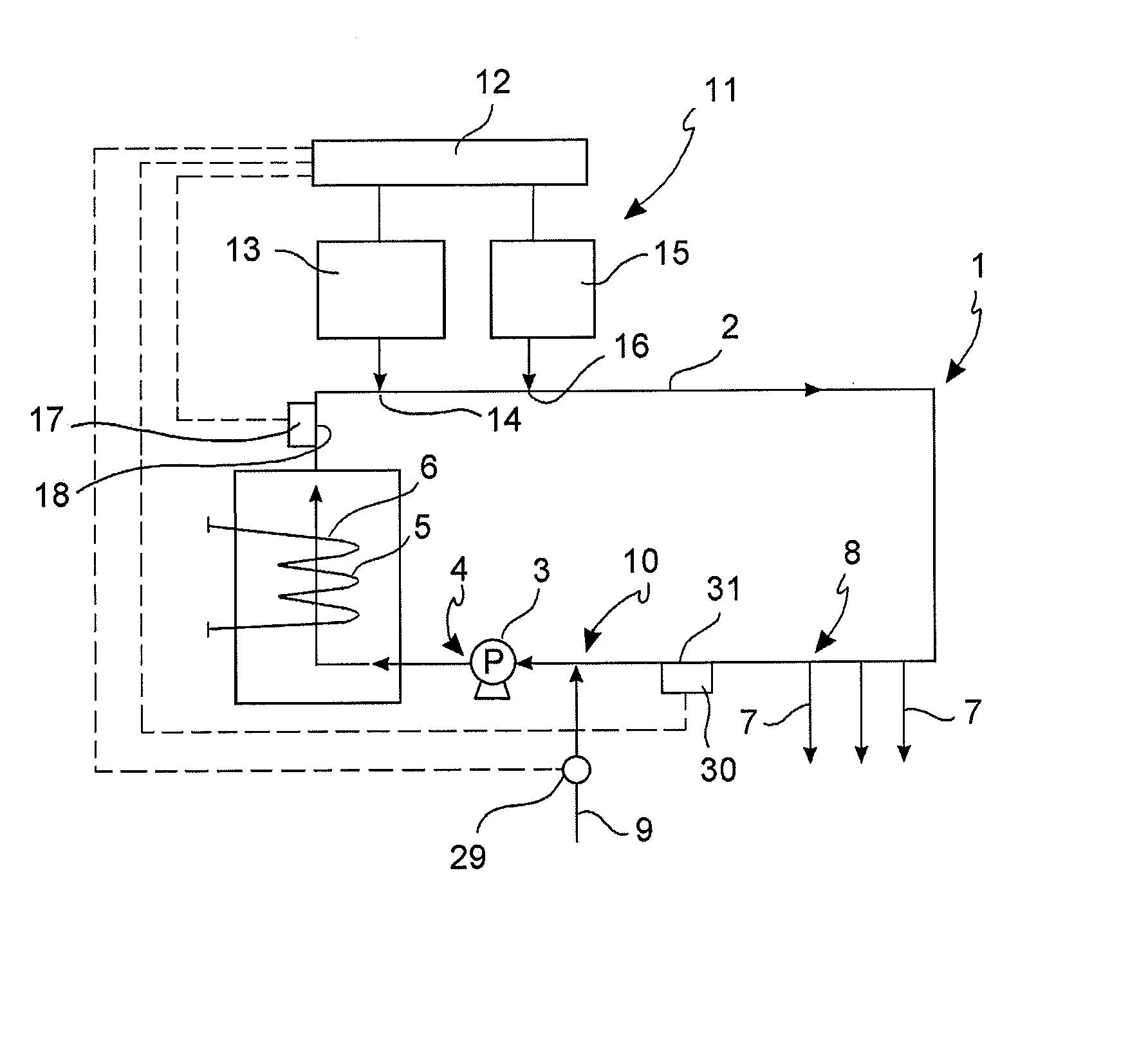
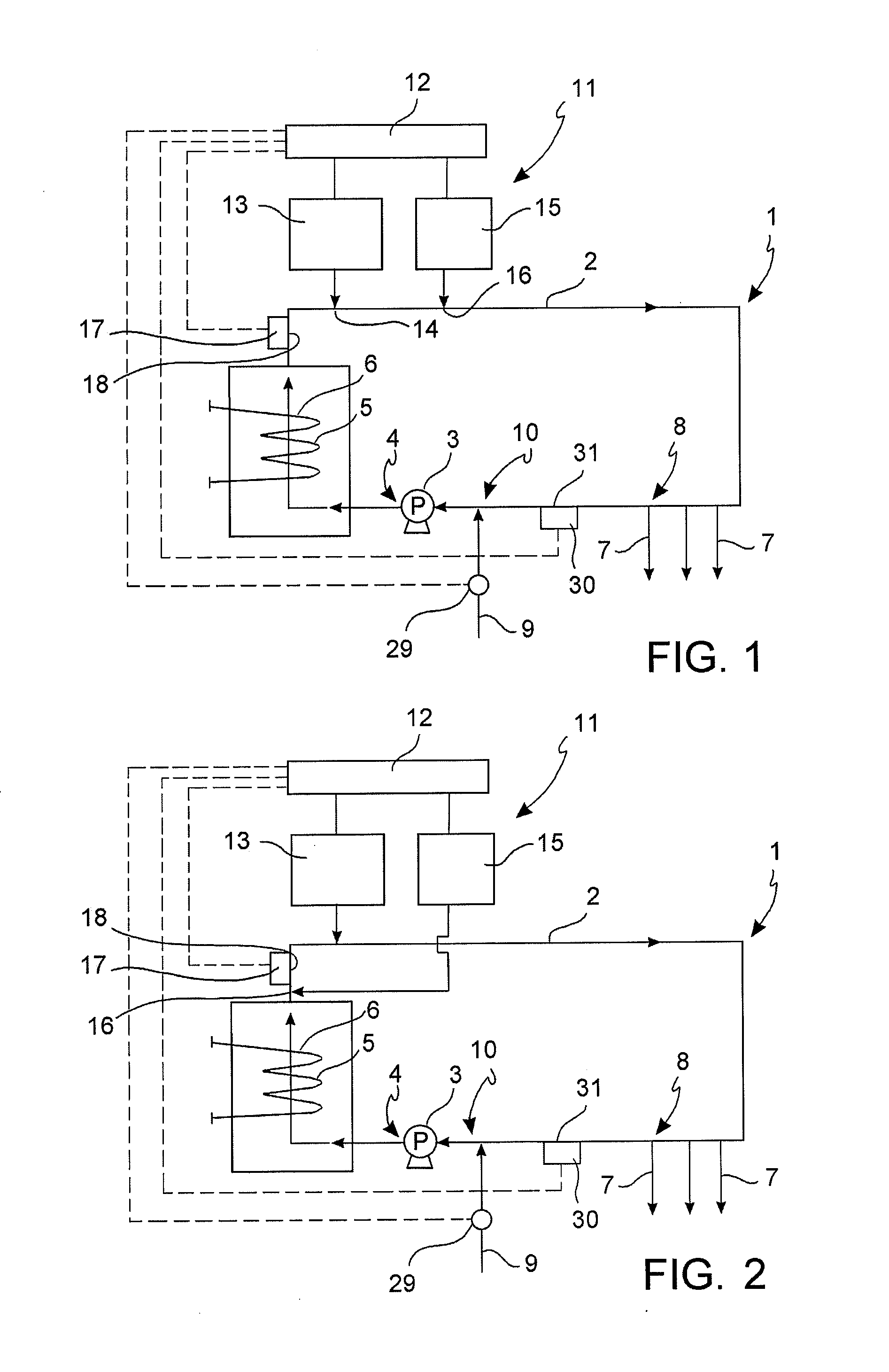
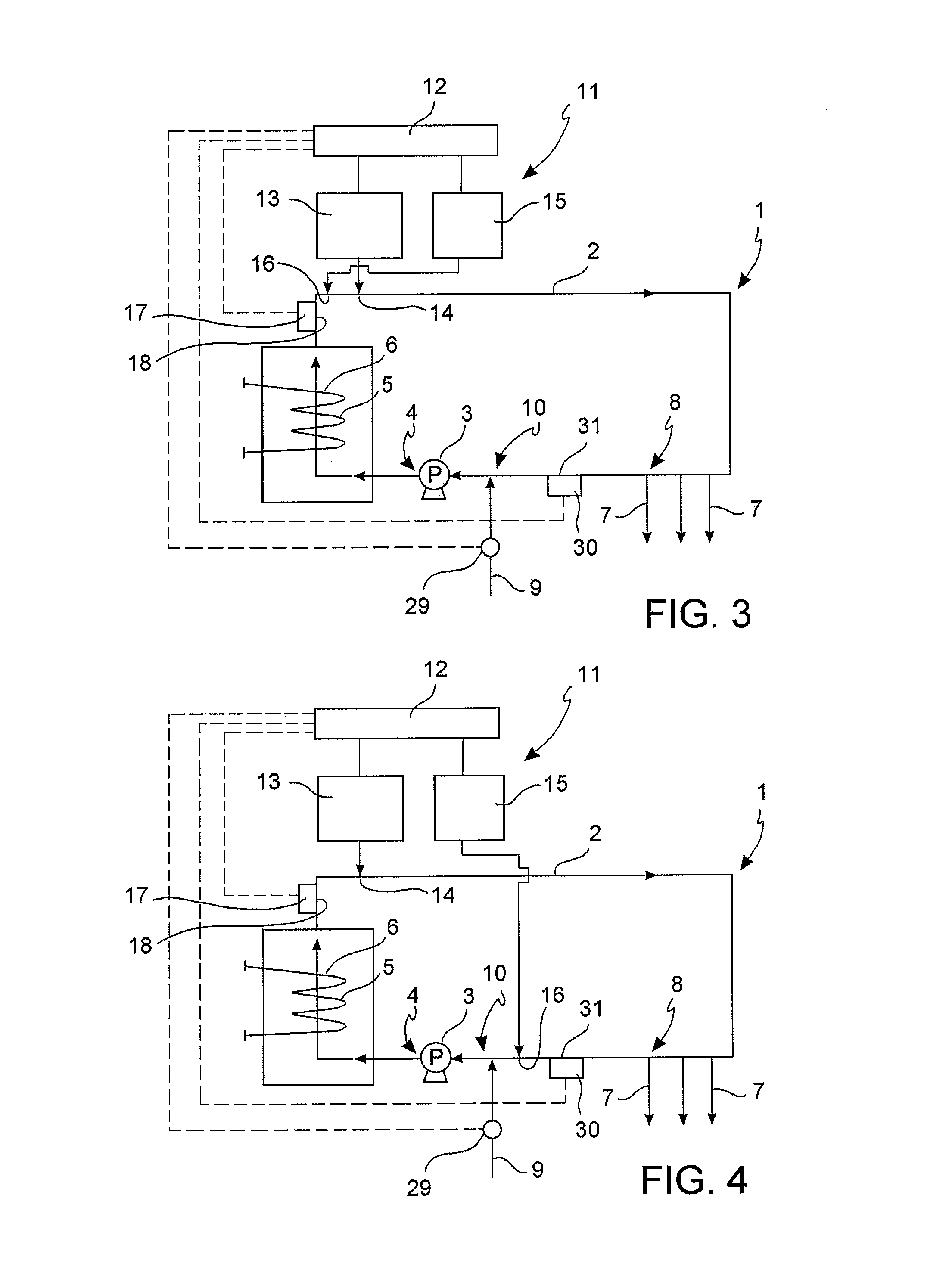
[0048]According to the invention, the method and disinfection system is applicable to warm water recirculating systems 1 comprising:[0049]an annular water duct 2,[0050]a pump 3 connected to the annular duct 2 at a pumping point 4 to make the water circulate in the annular duct 2,[0051]heating means 5, such as an electric or gas boiler, connected to the annular duct 2 in a heating point 6 and configured to heat water upon its transit through the heating point 6,[0052]one or more withdrawal ducts 7 connected to the annular duct 2 at respective withdrawal points 8,[0053]a supply duct 9 connected to the annular duct 2 at a supply point 10,[0054]optionally, a water tank connected to the annular duct 2.

[0055]In normal use of the recirculation system 1, the pump 3 makes the water circulate in the annular duct 2 through the heating means 5 which heat it to keep the water temperature within a predetermined range. The warm water is made available to users through the withdrawal ducts 7 and th...


PUM

PropertyMeasurementUnit
temperaturesaaaaaaaaaa
temperatureaaaaaaaaaa

Abstract

A sanitary warm water system comprises an annular water duct, a pump, a heater, withdrawing ducts connected to the annular duct and a supply duct, a monochloramine generator which synthesises and adds monochloramine to the warm water in the annular duct at a disinfection point, an ammonium ion abatement device which adds chlorine or hypochlorites to the warm water in the annular duct, an ammonium detector which detects the concentration of ammonium ions in the warm water and a control system which activates the monochloramine generator and activates the ammonium ion abatement device and controls the addition of chlorine or hypochlorite as a function of the ammonium concentration signals, independently of the activation of the monochloramine generator.

Description

BACKGROUND OF THE INVENTION[0001]1. Field of the Invention[0002]The present invention relates to a method and system for the disinfection of sanitary warm water.[0003]2. Description of the Related Art[0004]The warm water used for hygienic and sanitary, but also for technical, industrial and zoo-technical purposes may harbor microorganisms dangerous to human health, such as Legionella present in warm water and responsible for a bacterial infection, Legionellosis, which can strike humans with a high mortality rate, especially in a hospital setting.[0005]In water at moderate temperatures, not exceeding 30° C., Legionella can be found naturally in very low concentrations, considered non-critical from a health point of view.[0006]In warm water instead, at temperatures up to about 65° C., Legionella proliferates significantly, reaching concentrations dangerous for human health.[0007]As a result, the warm water for sanitary and technical use, for example in the range from 45° C. to 50° C.,...

Claims


Application Information

Patent Timeline
Patent Type & Authority Applications(United States)
IPC IPC(8): C02F1/76
CPCC02F1/76C02F2303/04C02F2305/02A01N59/00A61L2/18C02F2103/42C02F2209/005C02F2209/04C02F2209/14C02F2209/29C02F2307/14
Inventor GARUSI, GIANFRANCOGARUSI, FRANCESCO
Owner SANIPUR
Why Eureka
Try Eureka